
Get in touch with ECOFILTRONE™ Company




By DD · Updated October 2026
Combining a large-format liquid filter with a construction chosen for elevated temperatures, High Temperature High Flow Filter Cartridges allow selection of the required outlet quality for the whole process cycle: cold start, hot running and restart after loading. A high water flow rate may give only a partial solution to the task.
A bank that appears generously sized at room temperature may leave little operating leeway when hot. Another bank may have an average flow that’s acceptable, while one path may carry too much. This guide will address these two issues using worked examples and then illustrate how to determine the direction of the trend of the system pressure and avoid mistaking that for a measurement of particle removal.
Start with the operating point. Identify the liquid, its temperature and viscosity, the flow basis, the required removal performance and the complete housing arrangement. Keep the element’s structural pressure limit separate from the site’s operating allowance and replacement criteria.
What changes when high flow meets high temperature?

High-flow hot-liquid filtration combines two different design questions: how a cartridge handles the required flow, and how its complete assembly tolerates the process. Extra pleated area can reduce the number of elements needed in a suitable housing. Temperature suitability is dependent on the material selected, the fluid compatibility and the limits of the process. The HSE guidance on pressure systems likewise calls for knowing the fluid’s temperature and pressure and the equipment’s safe operating limits.
Many high flow pleated filter elements with filter media are designed for radial liquid flow. The radial flow path, pleat spacing and internal support affect how much of that area the liquid can use. Large flow demand still needs a product-specific curve. A high-capacity format, therefore, requires an actual pressure-flow curve of the length and grade instead of using a capacity ratio of another series.
Can high temperature filter cartridges handle high flow rates?
Yes, a correctly chosen hot-service component can handle a high level of flow rate within its operating limits. Use the manufacturer’s curve for the exact element and condition of the liquid. The maximum flow rate is a ceiling with a stated basis; the selected operating point must also satisfy pressure loss and outlet quality requirements.
Consider a hypothetical process water loop, where the production team requires the same delivered water flow before and after warm-up. Replacement of a large diameter item in the vessel is available. The cold-start curve is still required by Operations. The required particle-removal result at the hot condition is required by Quality. The purchasing decision remains open until those requirements meet at one operating point. Adding pleated area may help the hydraulics; increasing area alone does not qualify the seals or establish the removal efficiency. Before committing to the next planned shutdown, the purchasing team asked each bidder to price an identical complete interface and duty. That way, an inexpensive element with an unresolved adapter and/or seal won’t be the apparent winner.
Flow direction is a product-family feature. Large cartridges are supplied with different internal arrangements; ‘inside to outside’ flow shouldn’t be assumed from the words ‘high flow’. If a catalogue table and installation text contradict each other, ask the supplier to reconcile the controlled drawing and installation text before making a replacement.
Design-wise, a 60-inch element and a 2.5 inch cartridge are completely different. Length alone does not define useful area, housing fit or hot-liquid capacity. Look at the complete design of each proposed high flow series first, then use its qualified curve to determine how many elements the duty requires.
Which filter materials and components suit hot liquids?
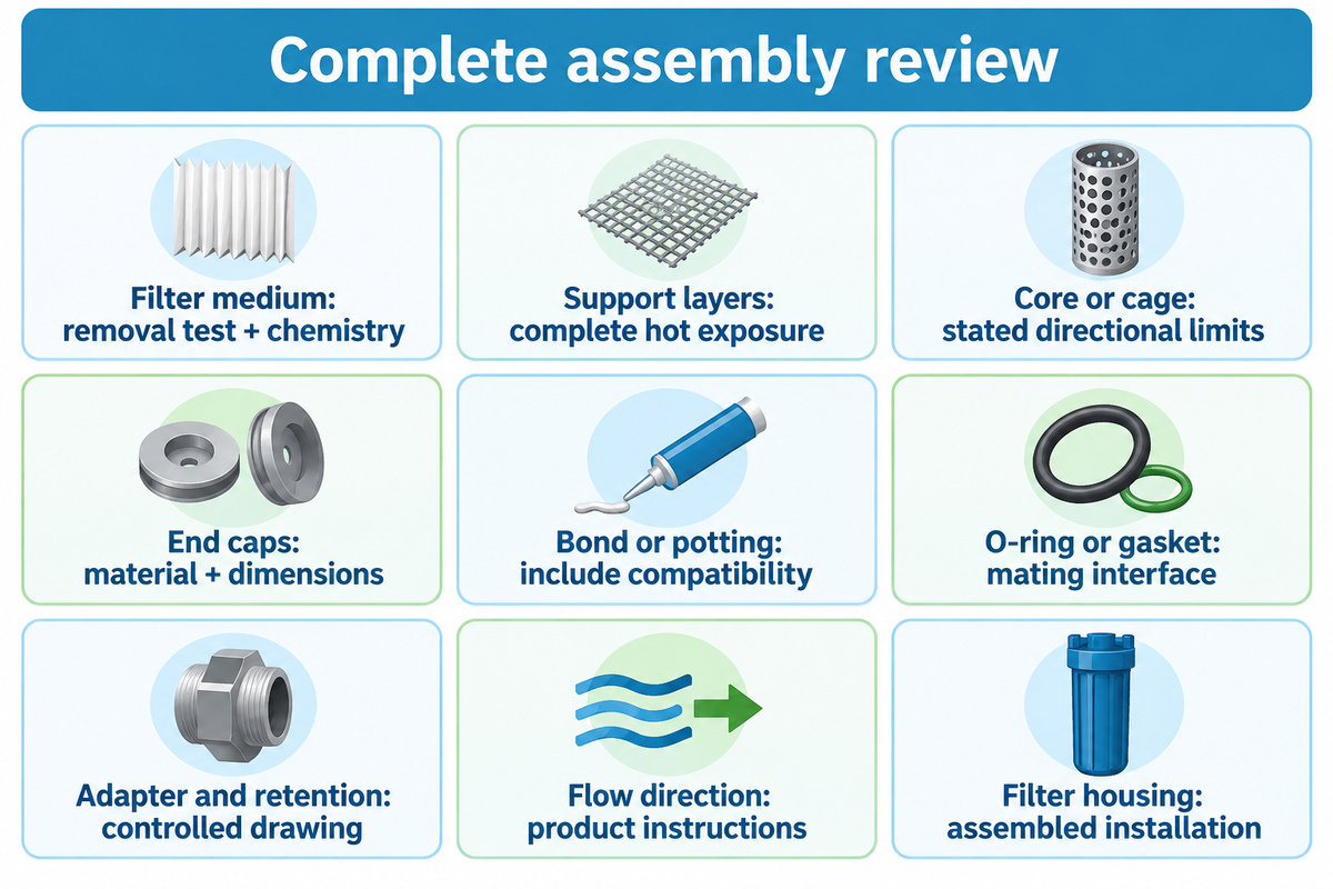
The selection of the hot-liquid filter starts with the complete wetted assembly. It shouldn’t be the name of the media that creates the ranking. PBT, glass fiber and polypropylene (PP) can describe different assembly components, and supports, bonds, end caps and seals can set a different limit. Compare these parts at the required chemistry and exposure time to determine which construction you’ll choose.
What materials are used in high temperature filtration?
In hot-duty cartridges, glass fiber media may be used with PBT-containing support layers, while polypropylene may be used as medium and support in another construction. Polyester may be used in support layers or with glass fiber media. The bill of materials should explain the role of each component. A glass-fiber medium with a polymer support, bond, or seal is a different assembly from one with a different support, bond, or seal.
Ask what limits the application. Chemical resistance at ambient temperature won’t settle prolonged chemical exposure when hot. A solvent or hydrocarbon mixture can alter the selection, along with oxidants or changing the concentration, even when the process temperature stays the same. For the larger material discussion, see our glass fiber pleated media and assembly guide.
| Part or feature | What to identify | Why the choice matters | Decision for the buyer |
|---|---|---|---|
| Filter medium | Glass fiber, polypropylene or another specified medium | Particle capture and fluid contact | Match the removal test and chemistry |
| Support layers | Polyester, polymer mesh or other support | Pleat support and flow access | Check the complete hot exposure |
| Core or cage | Material and structural arrangement | Directional differential-pressure strength | Use the assembly’s stated limits |
| End caps | Actual polymer or other construction | Mechanical load and sealing interface | Confirm material and dimensions |
| Bond or potting | Weld, adhesive or molded joint | Joint compatibility and durability | Include it in the material review |
| O-ring or gasket | Compound, size and seal geometry | Fit under the intended environment | Match the mating interface |
| Adapter and retention | Open end, closed end and locking features | Bypass prevention and installation | Compare the controlled drawing |
| Flow direction | Inlet, outlet and supported direction | Pressure loads act on different faces | Follow product-specific instructions |
| Filter housing | Vessel, internals, seals and connections | System pressure and separate hydraulic loss | Evaluate the assembled installation |
A defined test basis is required for high filtration efficiency claims. A micron label identifies another issue. Compare the defined efficiency at that particle size, the test method and the exact element tested. A 20 micron designation and a 1 micron designation aren’t the same just because both cartridges fit. See our micron-rating and retention explanation for that distinction.
A quoted 120°C maximum also needs its duration, liquid and pressure conditions. Treat the number as one coordinate of a specified duty, rather than permission to run every compatible-looking assembly continuously at that temperature.
Read temperature, pressure and exposure as one envelope
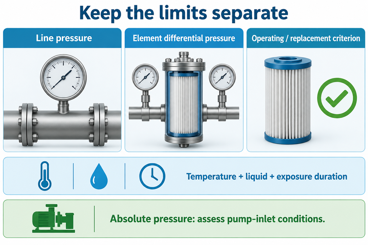
High temperature water service needs a stated duty. A hot-service operating envelope joins temperature, pressure, liquid chemistry and exposure duration for the complete installation. Continuous operation, a short excursion and cleaning are different duties. Line pressure, element differential pressure and a routine replacement criterion must stay separate, because each describes a different load or operating decision.
Pressure-systems guidance from the UK HSE highlights the fluid, pressure, equipment and operating conditions, as factors in deciding equipment suitability. That’s useful engineering context and the HSE guidance is in the context of the UK Regulations and doesn’t assess a cartridge’s pressure-at-temperature rating.
Consider pressure entries in the order of vessel pressure at the prevailing conditions; the forward and reverse differential limits of the element being assessed; and the operating and changeout conditions, as agreed. A room-temperature maximum differential pressure and a separate maximum temperature must not be combined into an unlisted hot operating point.
A buyer comparing two otherwise similar offers should ask whether the quoted temperature covers the complete proposed campaign or only a short exposure. The practical consequence is a different approved duty, even when the dimensional drawing is identical. The hot-liquid pleated-filter operating guide explains this in more detail.
Absolute pressure needs a separate check. The Hydraulic Institute’s explanation of pump suction head connects pump inlet liquid pressure to vapor pressure. A filter within its differential pressure allowance doesn’t necessarily establish adequate pump inlet conditions, and more specifically adequate pump suction conditions. The responsible system engineer must assess the phase state and required suction margin.
For a proposed 90°C continuous duty, request the simultaneous pressure and liquid conditions for that 90°C case. A short duration temperature condition may answer a different question. Generally, keep the vessel rating, differential limit and operating/replacement points on separate lines to allow like for like comparison.
Size the bank for cold start and hot operation
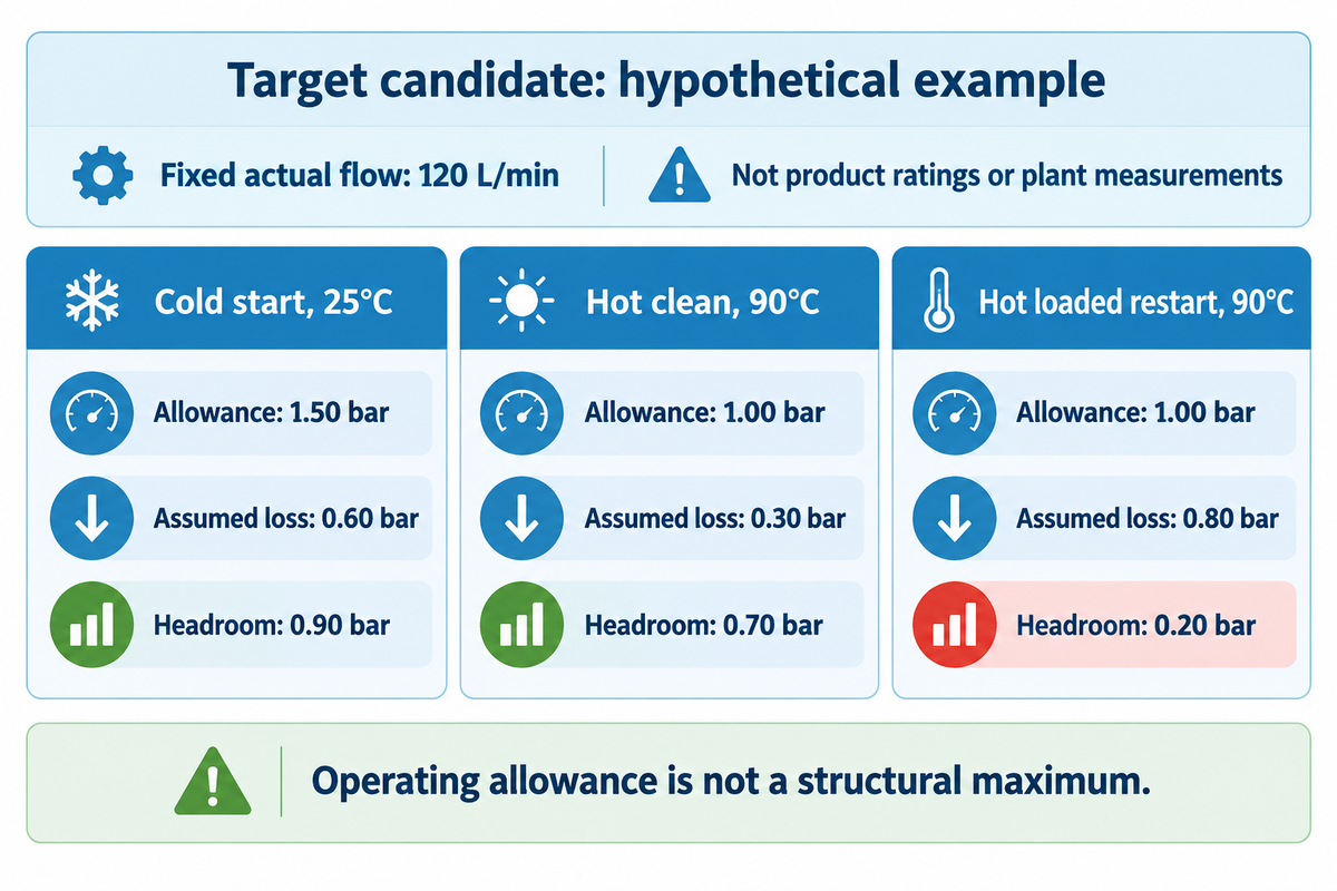
Bank sizing should consider both cold starts and hot operations, as well as loaded restarts at required flow, with matching pressure boundaries. The least remaining operating allowance can govern the choice even when hot liquid produces a lower clean pressure drop. Element curves, housing losses, and site approved operating criteria provide the basis of sizing.
The public scope of ISO 3968:2017 describes pressure-flow measurements at different flows and viscosities, including relevant assembly parts and valves. The hydraulic-filter standard remains current following its 2023 confirmation; it is a measurement framework, not a hot-water product approval.
Indicate on the drawing whether the curve represents the element only or the whole housing. Add housing and connection losses on the correct basis when evaluating the system; do not subtract a cartridge-only measurement from a whole-installation allowance and call the result spare capacity.
Indicate if mass flow or volume flow is being measured and give the temperature and pressure at the time of measurement. NIST’s fluid property reference indicates density and viscosity are separate properties. If mass throughput is constant, the actual volume throughput (L/min) will be different if the density changes. A viscosity correction does not perform that conversion.
Cold-Hot Pressure Headroom Chart
The following worked example assumes three candidates at a fixed actual flow of 120 L/min in each state. All losses and allowances are invented inputs, not product ratings or plant measurements. Assume the site has approved a 1.50 bar operating allowance when cold and 1.00 bar when hot, measured across the entire complete assembly. These operating allowances are separate from structural maximum ratings.
Remaining headroom = approved operating allowance – observed or predicted assembly loss. In this example, we assume the coarse candidate fails the required outlet quality, while the target and fine candidates meet it. The table therefore tests both pressure margin and the cost of selecting unnecessary resistance.
| Candidate | Operating state | Allowance, bar | Assumed assembly loss, bar | Headroom, bar |
|---|---|---|---|---|
| Coarse | Cold start, 25°C | 1.50 bar | 0.40 bar | 1.10 bar |
| Coarse | Hot clean, 90°C | 1.00 bar | 0.20 bar | 0.80 bar |
| Coarse | Hot loaded restart, 90°C | 1.00 bar | 0.65 bar | 0.35 bar |
| Target | Cold start, 25°C | 1.50 bar | 0.60 bar | 0.90 bar |
| Target | Hot clean, 90°C | 1.00 bar | 0.30 bar | 0.70 bar |
| Target | Hot loaded restart, 90°C | 1.00 bar | 0.80 bar | 0.20 bar |
| Fine | Cold start, 25°C | 1.50 bar | 0.90 bar | 0.60 bar |
| Fine | Hot clean, 90°C | 1.00 bar | 0.50 bar | 0.50 bar |
| Fine | Hot loaded restart, 90°C | 1.00 bar | 0.95 bar | 0.05 bar |
For the target candidate, the hot clean loss falls from 0.60 to 0.30 bar, yet headroom falls from 0.90 to 0.70 bar because the assumed allowance also falls. The loaded restart leaves 1.00 − 0.80 = 0.20 bar. Operations would focus its next review on that restart; quality would reject the coarse option despite its larger margin. Finance can question the fine option’s extra resistance when its additional removal is unnecessary. None of the positive margins alone approves a real installation. The next supplier discussion should address the loaded condition, not merely repeat the clean curve. A representative restart observation and a confirmed outlet result would resolve more of this purchasing decision than another headline maximum-flow number.
Substitute every input with the agreed site criteria and qualified curve for the selected grade. Failing to resolve restart transients and/or outlet requirements results in unresolved uncertainty for the selection. The high-flow cartridge qualification guide provides the scope and framework for the remaining documentation.
Why do parallel cartridges load unevenly?
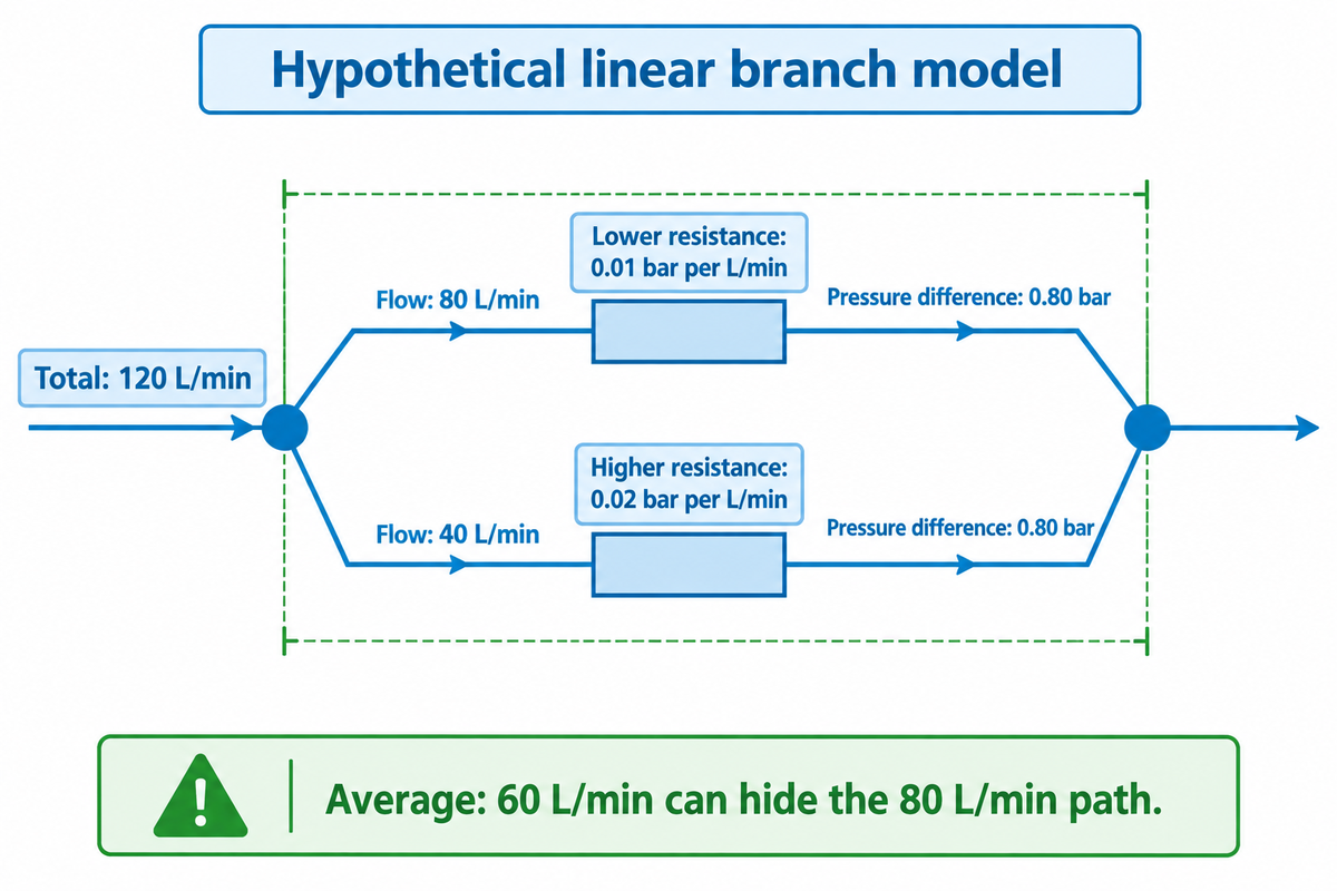
Parallel filter paths can share the same endpoint pressure difference while carrying different flows. Flow changes are brought about by resistance or loading differences and local header conditions. Dividing the total flow by the cartridge count yields an average; branch curves and measurements are required to determine what the most heavily loaded path actually carries.
A useful distinction separates flow between filter elements from flow within one element. In their original pleated-membrane model, Sun and colleagues showed spatially variable fouling along a pleat. In 2019, they published a preprint that assumes a dilute incompressible Newtonian feed and simplified densely packed pleats. It shows why equal branch flow doesn’t demonstrate uniform use of the media area.
Unequal-Branch Flow Split
Assume two idealized branches obey the linear law ΔP = R × Q, have identical pressure endpoints and carry a fixed total of 120 L/min. Assign resistance values of 0.01 and 0.02 bar per L/min. The second branch has twice the resistance, so the first takes twice its flow.
| Branch | Assumed resistance | Calculated flow | Pressure check |
|---|---|---|---|
| Lower resistance | 0.01 bar per L/min | 80 L/min | 0.01 × 80 = 0.80 bar |
| Higher resistance | 0.02 bar per L/min | 40 L/min | 0.02 × 40 = 0.80 bar |
It follows that the total flow is 120 L/min and the first branch flow is twice the second: 80 L/min and 40 L/min, respectively. If the hypothetical permitted branch flow were 70 L/min, the average would hide a path above that limit. The bottleneck is the lower resistance branch, despite spare arithmetic capacity in the other, higher resistance, branch.
Evaluating a real bank would mean replacing those assumed resistances with branch curves and including losses in the inlet distributor, local manifolds and valves. Industrial pressure-flow behavior can be nonlinear; the local end point pressures may not be equal in two branches even though they’re connected to a common header. The illustration keeps liquid properties and temperature constant and focuses on the branches. It doesn’t evaluate a cartridge’s rated flow, changing dirt load or internal pleat utilization. Compare an unloaded bank with the intended loaded condition, since a balanced arrangement may become unbalanced. When a branch cannot be measured, request a validated network assessment rather than consider the average as its measurement.
A historical pressure-leaf-filter discussion describes a practical consequence of unequal loading: flow can move toward the cleaner path as another path loads. That observation is useful as a monitoring question, rather than a prediction for every cartridge bank. A spare element on a shelf is also different from a separately isolatable standby bank.
At 120 L/min, a two-path average of 60 L/min can conceal an 80 L/min path in the stated linear example. Use the most constrained approved path when evaluating bank capacity. Use only manufacturer-approved arrangements for unused cartridge positions and standby isolation inside a shared pressurized housing.
Diagnose filter pressure before a cartridge change
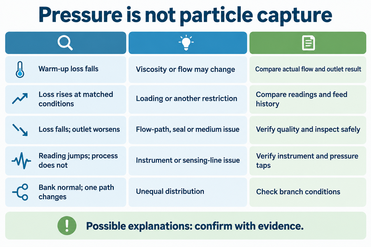
A filter-pressure trend is most revealing when combined with other data trends (e.g. flow, temperature) and outlet quality using a consistent measurement boundary. Increased loss may indicate a change in the process or increased loading; decreased loss may be the result of less flow, warmer liquid, or a different flow path. Pressure alone isn’t a measure of the cartridge’s filtration efficiency. Judge filtration performance against the independent outlet requirement.
The original hydraulic and fuel-filter tests reported by Gregory LaVallee and Philip Johnson of Donaldson compared steady, cyclic, and vibrating conditions. In 2003, their findings varied with the type of fluid and loading. Those adjunct-system tests warrant review of the operating history; they don’t confirm that warming always reduces capture in an approved hot-water cartridge.
“Reliable results are achieved only if they are calibrated and matched.”
The IFTS authors explain that sampling flow and pressure changes can affect particle-count results. For consistent filtration, quality should specify a measurement suitable for the liquid and acceptance requirement, rather than use an unvalidated sensor reading to settle a suspected failure.
| Observed pattern | Possible explanation | Evidence to compare |
|---|---|---|
| Loss falls during warm-up | Viscosity or flow changes | Actual flow, liquid condition and outlet result |
| Loss rises at comparable conditions | Loading, an upset or another added restriction | Matched-state readings and feed history |
| Loss falls with poorer outlet quality | Changed flow path, sealing problem or damaged medium | Independent quality result and inspection under approved isolation |
| Reading jumps without a matching process change | Instrument or sensing-line issue | Instrument verification and pressure-tap condition |
| Bank readings look normal but one path changes | Unequal distribution | Branch conditions and local measurements |
Do high temperature filters require special maintenance?
Hot-service replacement requires the correct part, control of the isolation and consideration of the exposure history. Site energy control procedure and equipment instructions should be followed prior to opening the equipment for inspection. A cooler gauge reading alone doesn’t indicate a vessel is safe to open. Universal calendar intervals and unauthorized cleaning are to be avoided.
How do you ensure consistency in filter cartridge performance?
Consistent performance requires the same evaluation criteria and a record of flow, temperature, pressure boundary and loading history. Check structural integrity and filtration efficiency according to separate requirements. For the hypothetical chart, compare a loaded restart at 90°C to a later evaluation with the same 90°C state, rather than to an unrelated cold reading.
When is another filtration route the better fit?
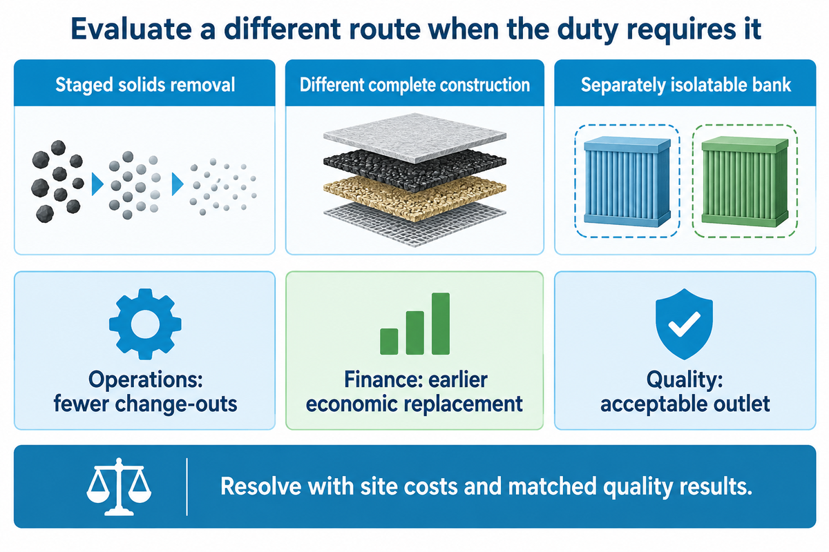
There are alternative routes for filtration that become worth evaluating when the required outlet quality, solids loading or operating envelope makes the proposed cartridge arrangement inefficient or unsuitable. Staged solids removal, a different complete construction or a separately isolatable bank may solve different constraints. Compare the process results and operating costs before deciding on a nominal flow increase.
Water filter cartridges are available in different designs. A standard pleated element, a string-wound element and a serviceable stainless steel filter are other options. A wound sediment filter may address a solids challenge, but a sediment filter cartridge can’t be chosen for a corrosive hot stream, based on its size designation. Other things, like cleaning access and chemical compatibility, may be more important than the apparent saving in capital cost.
Before selecting another standard filtration option for high dirt loads, review pre-filtration and the upstream contamination source before repeatedly replacing the final cartridges. Pumping systems resources provided by the Department of Energy can help to frame the pump performance at the system level. Resistance in the element alone won’t necessarily indicate the motor is saving electricity; the control method, the flow and other losses also matter.
An original 2020 desalination study by Farhat and colleagues compared seven cartridge types and evaluated replacement economics at 0.05, 0.15 and 0.25 €/kWh. Within the study’s parameters and model, optimized replacement timing offered further cost savings of 2% to 16%. The lesson is a purchasing tradeoff: a longer run can accumulate pressure-related cost. The percentages and historical tariffs aren’t projections or expected savings for a hot industrial loop.
Operations can favor fewer change-outs while finance advocates for an earlier economic replacement point; quality dictates the acceptable outlet. Resolve that tension with representative site costs and matched quality results. For a separate mechanism, refer to our depth-filter loading and selection guide prior to assuming that every solids problem requires the use of a finer pleated element.
Turn the guide into a matched replacement request

The best replacement request should describe the physical fit and the hydraulic requirement and the level of quality of the outlet for a defined operating cycle. Provide the supplier with the limiting condition rather than a photograph of the part. The best offer should explain how the proposed assembly would meet the limiting condition and what evidence would be provided to prove the assembly is acceptable.
In industrial environments, report any corrosion found during maintenance as part of the replacement history. Include the controlled drawing, complete wetted materials, liquid composition, actual flow basis and the cold, hot and restart conditions. Name the measurement boundary and the quality method required. A 0.5 micron request, for example, still requires its defined efficiency and test basis; a hydraulic test designation alone doesn’t establish water-cartridge approval.
At ECOFILTRONE™, we provide application review, filter selection, specification verification and replacement matching for industrial liquid filtration. Our engineering support can assist in organizing datasheets, drawings and customized configurations around the stated duty. We review compliance documents requested against the exact product and the actual certificate holder.
For a specific request, please refer to our high-temperature high flow cartridge configuration page for available configurations and duty-specific selections. The information in this guide prepares your operational questions; that solution page addresses product questions.
Bring the condition that limits your choice. Share the cold-start flow, hottest operating condition and loaded-restart pressure loss, together with your required outlet result. We can review the proposed filter configuration, replacement fit and supporting technical documents against those application requirements.
Frequently Asked Questions
What temperatures can high temperature filter cartridges handle?
The allowable temperature comes from the exact cartridge assembly, liquid, pressure and exposure duration.
Separate the continuous-duty limit from short excursions and cleaning exposure. Supports, end caps, bonds and seals can govern before the medium does. Obtain the simultaneous pressure-at-temperature conditions for the proposed part. A maximum temperature printed elsewhere in a series brochure does not extend every configuration’s operating envelope or authorize a different chemical duty.
How long do high temperature filter elements last?
Hot-service element life follows the actual loading and acceptance criteria, rather than a universal number of months.
Track comparable-state pressure loss, throughput and outlet quality through the representative operating cycle. A contaminant upset can shorten a run, while a different grade may change both capture and resistance. Base replacement on the approved process and equipment criteria. Published lifespan gains from another plant remain that plant’s result, not a guaranteed service interval.
Where are high temperature filter elements commonly used?
Hot-liquid elements serve selected process-water, condensate and chemical-processing particle-removal duties.
The application name alone does not select the assembly. Food and beverage, power-generation and other industrial water systems may have different chemistry, cleanliness and documentation requirements. Check the liquid phase, required removal and hottest simultaneous pressure condition. A hot-water prefilter’s suitability does not qualify a downstream membrane, or establish pharmaceutical or food-contact compliance for another product.
Can a cartridge remove dissolved salts from hot water?
A particle-filter cartridge targets suspended material; dissolved-salt removal requires an appropriate separate treatment mechanism.
Define the contaminant before choosing the rating. Visible scale particles and dissolved ions are different targets. Evaluate desalination, ion exchange or another suitable process for dissolved species, with the required temperature conditioning and treatment-system design.
Can a hot-service cartridge be cleaned or backwashed?
Cleaning or backwashing is appropriate only for a construction and system expressly designed for that method.
Disposable pleated cartridges should not be treated as reusable solely because they withstand the process temperature. Reverse flow, cleaning chemistry and repeated exposure impose different conditions from normal filtration. Obtain the product-specific procedure and criteria for returning the element to service. If frequent cleaning is essential to the economics, evaluate a serviceable filter arrangement from the outset. Compare the resulting outlet quality and operating burden with a disposable option before choosing the route; avoid improvising a backwash sequence.
What affects the purchase price of a hot-service high-flow cartridge?
Quoted price reflects the specified materials, dimensions, removal requirement, interface and supporting documentation.
Compare identical duties and supply scopes before comparing unit prices. Include the housing arrangement and replacement frequency in the purchasing review. A premium cannot be justified by an unqualified temperature label or an assumed service-life improvement.
Are hot-service high-flow cartridges worth the extra cost?
A higher-priced cartridge is worthwhile when its matched performance improves the actual process economics while meeting the required quality.
First establish that the proposed duty needs the construction and that the alternative is genuinely comparable. Then evaluate consumables, change labor, disposal, pressure-related energy and downtime using representative site data. Keep the quality criterion fixed throughout the comparison. Longer service life is useful only while acceptable filtration continues. If the process can use a simpler compatible assembly without losing output or quality, a higher temperature label alone provides no financial reason to upgrade.
References & Sources
- Pressure systems: Safety of pressure systems UK Health and Safety Executive.
- Reliability Basics: Understanding NPSH, POR, and AOR Hydraulic Institute, 2022.
- ISO 3968:2017, Hydraulic fluid power, Filters, Evaluation of differential pressure versus flow International Organization for Standardization; confirmed 2023.
- Thermophysical Properties of Fluids Eric W. Lemmon, National Institute of Standards and Technology, 2009.
- Modeling and design optimization for pleated membrane filters Sun, Sanaei, Kondic and Cummings, 2019 preprint.
- How Flow and Vibration Affect Filter Performance LaVallee and Johnson, Machinery Lubrication, 2003.
- Filter testing: Automatic Particle Counters and Fluid Contamination Monitors Peuchot, Lynch and Petillon, Filtration+Separation, 2011.
- Pumping Systems US Department of Energy.
- Cartridge filter selection and replacement: Optimization of produced water quantity, quality, and cost Farhat and colleagues, Desalination, 2020; TU Delft research record.