
Get in touch with ECOFILTRONE™ Company




Cooling Tower Side-Stream Filtration is the removal of suspended particles from a portion of recirculating tower water. The treated branch returns water to the system while the main cooling flow continues. Its practical value is in capturing transported solids, recording the operating burden and keeping water-treatment duties separate.
Cooling Tower Side-Stream Filtration treats a partial flow repeatedly. Particle capture, basin collection and incoming dirt determine cleanup. Filtration complements water treatment; it does not remove dissolved salts or replace microbiological control.
Key operating points
- One hydraulic turnover doesn’t mean every particle has passed through the filter.
- A smaller micron rating doesn’t correct poor basin pickup or an open bypass.
- Pressure readings become useful when recorded with actual branch flow.
- Filter discharge belongs in the water balance and the operating-cost calculation.
| Item | Operating meaning |
|---|---|
| Treatment target | Suspended organic and inorganic particles |
| Flow arrangement | Partial-flow branch with return to the circulating water |
| Core observations | Flow, differential pressure, comparable solids samples and basin condition |
| Separate duties | Dissolved-water chemistry, corrosion control and microbiological management |
How side-stream filtration works in an open cooling-water loop
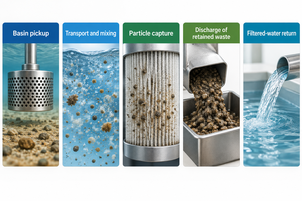
A side-stream filtration system draws water from a basin or circulating pipe and separates particles. It then returns treated water to the system. Repeated passes treat the shared inventory over time. Open cooling tower systems receive airborne material, so the filtration process works against a continuing input rather than cleaning a permanently sealed tank.
Cooling tower filtration removes solids before they add to deposits. As air and water meet during heat rejection, dust, fragments and other debris can enter the recirculating water, settle or foul surfaces. The partial-flow arrangement and principal technology options are described in the U.S. Department of Energy’s 2012 technical evaluation.
In a recirculating cooling installation, repeated recirculation brings suspended material back toward the treatment branch. The open tower circuit is different from the chilled water loop which is served through a heat exchanger. Place the side-stream filter on the intended circuit and label that connection in the operating record. For the element’s construction, see the pleated filter cartridges guide.
How does side-stream filtration differ from inline filtration?
Side-stream filtration treats a diverted portion of the circulating flow, while full-flow filtration treats the main flow through its defined path. The side stream filter can work repeatedly on the common inventory without passing all the circulation through that filter at a time. An inline strainer in the circuit may protect equipment locally rather than clean the entire tower inventory.
A clear filter outlet can coexist with sediment in a far basin corner because the branch treats only water reaching its inlet. In this hypothetical maintenance review, the filter doesn’t move that settled bed into the pickup. Trace the physical path in order: basin pickup, transport and mixing, particle capture, then discharge of retained waste. A restriction or short circuit at an earlier step limits what a finer element can accomplish. Compare basin locations during the same inspection, record the branch flow and consider the pickup arrangement when evaluating the result.
What filtration removes, and what remains a water-treatment duty
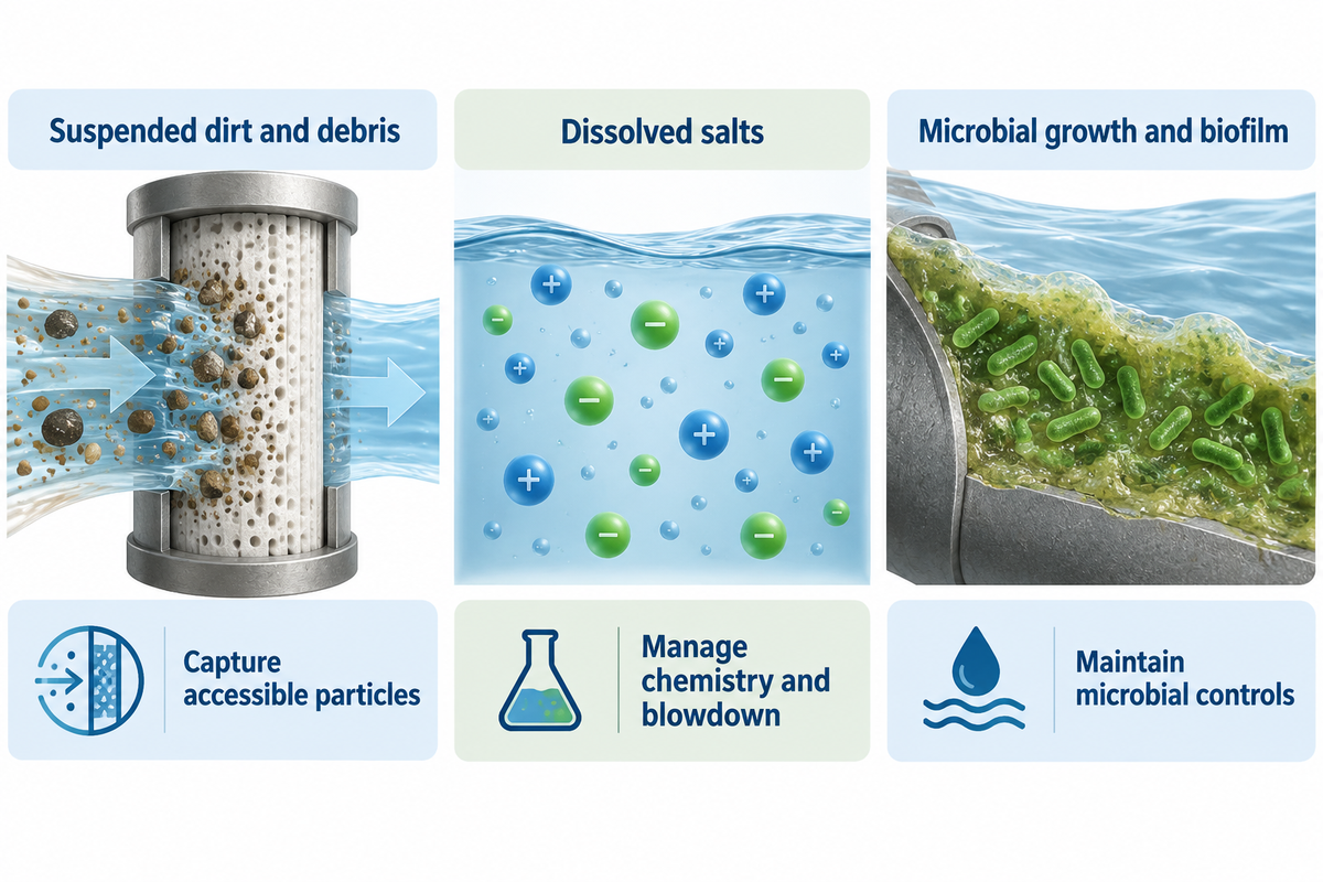
Filtration removes suspended solids that reach the separation device; dissolved salts continue circulating with the water. Water treatment therefore retains responsibility for scaling, corrosion and microbial control. Clear-looking cooling tower water can still contain dissolved contaminants and present a different condition from the deposits or biofilm attached to internal surfaces.
| Material or condition | Filter contribution | Remaining management duty |
|---|---|---|
| Suspended dirt and debris | Capture the accessible particle fraction | Inspect deposition, loading and waste removal |
| Dissolved salts | Conventional particle filtration leaves dissolved salts in solution | Manage conductivity, chemistry and blowdown |
| Microbial growth and attached biofilm | Removal of some suspended material supports housekeeping | Maintain the site’s water-management, cleaning and microbial controls |
Evaporation concentrates dissolved substances, so cycles of concentration remain a water-chemistry decision. Particle removal and dissolved-solids treatment serve different duties, as outlined in the Department of Energy’s current FEMP technology guidance; a biocide program also has a separate role.
“Side stream filtration does not remove dissolved particles.”
As part of the Legionella water management, sediment control is addressed in the CDC’s cooling-Tower Guidance. Cleaning and conditioning of systems, monitoring and treatment are other active responsibilities. Do not treat improved water quality by appearance as a microbiological release criterion.
Water samples and surface samples also represent different places. A 2026 study recorded by the University of Sheffield examined multiple cooling tower systems at one site and detected L. pneumophila in biofilms rather than bulk-water samples. That sampling distinction reinforces a practical boundary: a clear water sample isn’t an inspection of attached growth. The study examined microbial monitoring, not filter performance.
Which solids can different filtration technologies reach?

Centrifugal separators separate particles according to their properties and hydraulic conditions; media, screens and replaceable elements retain transported material through different structures. These side stream filtration technologies also release collected waste differently. Compare particle size distribution and loading pattern before using a nominal micron number to rank filtration solutions.
| Route | Separation mechanism | Operating evidence to record |
|---|---|---|
| Centrifugal separator | Uses centrifugal action; capture depends on particle size, shape and specific gravity relative to water | Branch flow, purge volume and particle classes remaining |
| Media or sand filter | Captures material within a media bed; layers of media and hydraulic loading affect behaviour | Differential pressure, wash sequence, backwash water and media condition |
| Automatic screen filters | Retain particles at a screen surface; cleaning removes the accumulated material | Screen condition, cleaning frequency and discharge |
| Bag or cartridge filter | Captures particles within or on replaceable filtration media | Clean and loaded pressure at comparable flow, element condition and replacement labour |
Maintenance of the separation mechanisms described in the DOE technical report varies with steady versus variable solids loading. The solids loading distinction is from the supplier-affiliated 2019 Water Technology article on side-stream and media filtration.
Backwashing removes retained material from a suitable media filter. A disposable element removes solids from water by trapping particles that are later removed with the element. Document the operating condition of each method (flow rate alongside service condition).
How efficient is side stream filtration?
Filtration efficiency describes removal of a defined particle class under stated operating conditions; whole-system cleanup also includes flow, incoming contamination and access to deposits. A filter, however, can behave differently by processing lighter material or a changing load. Compare inlet and outlet samples under the same operating conditions and follow the basin trend separately.
Fine particles, deformable material and changing hydraulic load can alter filtration efficiency. Compare a “high efficiency” claim based on its removal basis, test flow and stated threshold for particles of a given number of microns and larger. Pore or grain size alone cannot fairly compare a sand filter with a disposable cartridge.
For an operator comparing a bag with a finer cartridge, the immediate tradeoff is capture versus loading and service work. More retained material must leave the filter system through cleaning or replacement. Record whether the change reduces deposits at the protected heat exchangers, rather than counting a dirtier element alone as success.
Why a percentage of circulation does not define cleanup time
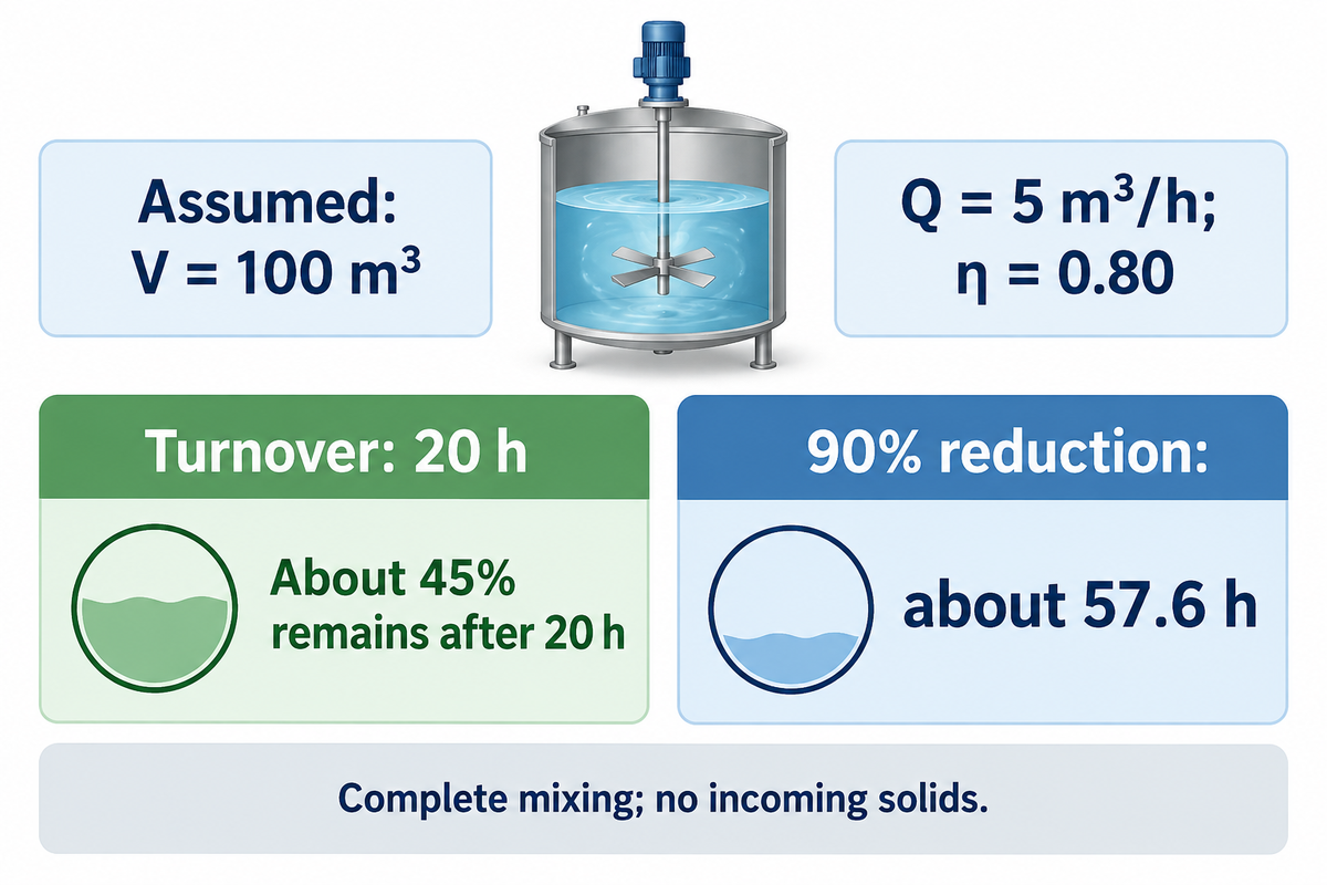
Side-stream flow expressed as a percentage of main circulation describes a hydraulic relationship rather than a cleanup time. Water inventory, particle capture, solids input and pickup location affect the result as well. The DOE Technical Report mentioned repeated partial-flow treatment. A branch treating a large basin can take much longer than one turnover to lower concentration, even in a perfectly mixed system.
System size should account for the circulating water inventory as well as the main circulation duty. A percentage of the latter alone leaves the inventory unstated.
How do I know which side stream filter is right for my cooling tower?
Match the mechanism of removal to the solids first: dense settleable material, lighter organic matter, and fine suspended material create different duties. Then define the concentration or deposition problem the site wants to correct. An engineer assesses the hydraulics on site; comparable samples and service records show if the selected arrangement is achieving the desired operating result.
The Suspended-Solids Removal Clock illustrates repeated partial-flow treatment and explains the difference between hydraulic turnover and particle clearance. The clock isn’t a sizing method for treatment units.
Assumed inputs: water inventory V = 100 m³; side-stream flow Q = 5 m³/h; capture fraction η = 0.80 for one chosen particle class. Assume constant volume, complete mixing, constant flow and capture, no incoming solids, and no settling or other removal. The capture fraction is an illustrative input, not a product rating.
Concentration remaining: C(t)/C(0) = exp(−ηQt/V).
Hydraulic turnover: V/Q = 100/5 = 20 h.
After 20 h: exp(−0.80 × 5 × 20/100) ≈ 0.449, so about 45% of the initial concentration remains.
Time for a 90% concentration reduction: ln(10) × 100/(0.80 × 5) ≈ 57.6 h under these assumptions.
One tank volume passing through a mixed loop does not mean every original particle has passed through the device. Previously filtered water mixes back into the inventory and can pass through again. With continuing dust input, concentration can approach a balance between the incoming and removed material rather than continue to decrease toward zero.
The ideal steady concentration is 5 g/m³ = 5 mg/L with an additional constant input of 20 g/h in the same illustration. Effective clearance is 0.80 × 5 = 4 m³/h, giving 20 g/h divided by 4 m³/h. For a tower-specific cleanup-time assessment, measure actual collection, particle behaviour and changing load.
Filtration performance: paired observations versus clear-looking water
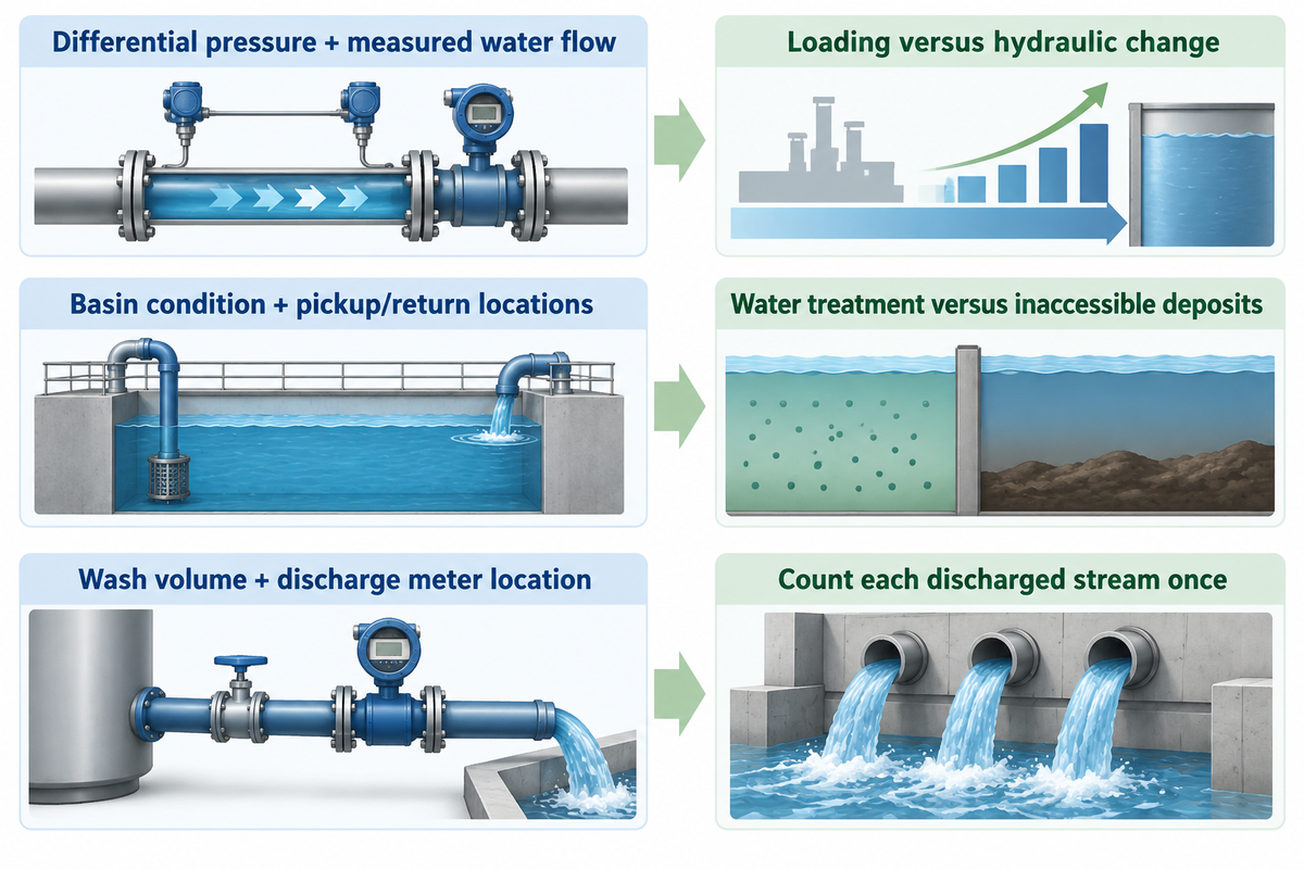
Cooling water evaluation requires comparable observations of solids paired with flow, pressure and operating conditions. A lone clear outlet sample describes that sample at that time. Matching locations and methods across a documented baseline and operating period makes changes easier to interpret, while separate basin observations show whether deposited material is actually being reached.
| Observation class and pairing | What the pairing helps distinguish | Record boundary |
|---|---|---|
| Differential pressure + measured water flow | Loading versus a change in hydraulic operating point | Same filter, gauge locations and valve arrangement |
| Inlet/outlet solids + particle size distribution | Removal of the measured particle fraction | Same sampling method and comparable operating time |
| Basin condition + pickup/return locations | Water-column treatment versus inaccessible deposits | Same inspection areas and tower operating state |
| Makeup/blowdown meters + conductivity | Water balance versus dissolved concentration | Identify which meter includes filter discharge |
| Service hours + changes of elements or cleaning | Calendar time versus actual maintenance burden | Include labour, disposal and downtime |
| Optical reading + laboratory solids result | Clarity versus mass concentration | Retain each method’s units; do not substitute one reading for the other |
| Bulk-water sample + surface inspection | Suspended material versus attached deposits | The water-management team controls microbiological evaluation |
| Electricity + cooling duty and weather | Power use versus a changed operating load | Same equipment, runtime and comparison period |
| Wash volume + discharge meter location | Filter-specific waste versus already metered blowdown | Count each discharged stream once |
Turbidity measures an optical property influenced by light scattering; total suspended solids measures material concentration on a different basis. The optical definition appears in the U.S. Environmental Protection Agency’s turbidity guidance. No universal conversion links an optical reading to mass concentration for every cooling-water sample.
Particle volume per water volume is different from measurement in mg/L and turbidity. The DOE report’s Oak Ridge example uses particle volume per water volume in Table 4.1; retain that measurement method and unit when comparing results.
Wash discharge is counted only once, regardless of how many times it passes through a blowdown meter. Map the backwash pipe onto the meter layout before calculating water loss and cost. For water use evaluation, refer to the Department of Energy’s cooling-Tower Management Guidance, which compares makeup/blowdown ratios with conductivity ratios.
Makeup water has its own chemistry and load of suspended solids. A change in raw water supply or pretreatment can change the tower’s starting conditions, so include it in the event log.
How often should cooling tower water be tested for particulate levels?
Use the site’s written monitoring schedule, and add comparable particulate observations around a filter trial, major dust event or operating change. Maintain the same sampling methods and locations for readings to be compared. Microbiological sampling follows the water-management program and responsible specialist’s instructions; a particulate evaluation does not replace that schedule.
In a trial log, record the date, operating hours, load condition, sample points and any cleaning between readings. A baseline sample taken after basin cleaning and a later sample taken after a dust event describe different starting conditions. Note those events beside the result rather than attributing the entire change to the filtration unit.
Read the operating symptoms before changing the filter
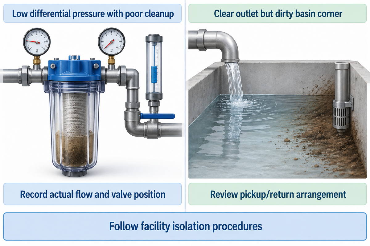
Filter pressure and water appearance help focus an investigation when compared to a known operating baseline. Rapid pressure increase can indicate a greater load, while a low pressure difference can indicate low flow. Treat the symptom as a reason to compare measurements. Don’t automatically change the level of filtration or replace the element.
Clean-filter pressure loss is attributed to media and flow; accumulated contaminants increase pressure differential. The University of Florida’s media-filter guidance describes these hydraulic principles for irrigation. While the numeric operating limits are specific to irrigation, the qualitative distinction is applicable here.
| Observed symptom | Possible explanations | Next observation and owner |
|---|---|---|
| Faster pressure rise after a dust event | Higher solids input; changed flow; different installed element | Maintenance compares flow and element identity with the clean baseline |
| Clear outlet but dirty basin corner | Settled solids do not reach pickup; return water short-circuits | System engineer reviews pickup/return arrangement and inspection locations |
| Low differential pressure with poor cleanup | Low branch flow; bypass path; a particle class the device does not capture | Maintenance records actual flow and valve position; engineer reviews the path |
| More frequent media-filter cleaning | Higher loading; changed hydraulic duty; ineffective wash | Authorized service staff compare wash conditions with equipment instructions |
Imagine a dusty week at an open industrial cooling tower. The service interval shortens, but the operator also changed the branch valve position. Comparing only days between replacements would combine two changes. The maintenance team records flow and pressure at the same points, checks the element reference against the previous installation and notes the dust event. The engineer can then compare the solids load and hydraulic condition separately. If the basin remains dirty in one corner while the sampled outlet improves, the pickup path becomes another question. A finer element would change capture and loading; it wouldn’t relocate the settled material.
Keep work on pressurized equipment within the facility’s isolation and maintenance procedures. The observation sequence above does not authorize opening housings, altering chemical controls or servicing a running filtration system.
What determines annual filtration operating burden?
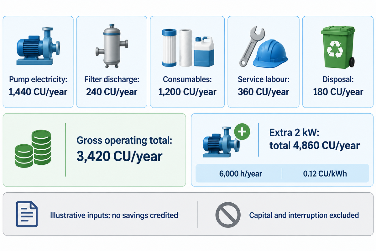
Annual filtration cost is a combination of the cost to pump water, the cost of water discharged, consumables, labor, and the cost to dispose of the waste over the same time period. Capital cost and the cost to interrupt service must be considered separately. Use measured electrical energy and service records, if available. The least expensive replacement element can still create a larger annual burden through frequent changes or additional pumping.
System efficiency should be evaluated at a comparable cooling duty with the filter’s own electricity included in the energy balance.
For a current cost comparison, use site tariffs and supplier’s prices and actual service requirements. The DOE report’s hypothetical economic example uses historical June 2012 prices.
Example: assume a pump draws 2 kW for 6,000 h/year at 0.12 currency units (CU)/kWh. Discharged filter water is 80 m³/year at a combined water-and-waste charge of 3 CU/m³. Consumables cost 1,200 CU/year; 24 service events each take 0.5 labour-hour at 30 CU/hour; disposal costs 180 CU/year. All inputs are illustrative, with no savings credited.
| Cost item | Calculation | CU/year |
|---|---|---|
| Pump electricity | 2 × 6,000 × 0.12 | 1,440 |
| Filter discharge | 80 × 3 | 240 |
| Consumables | Annual assumed total | 1,200 |
| Service labour | 24 × 0.5 × 30 | 360 |
| Disposal | Annual assumed total | 180 |
| Gross operating total | 1,440 + 240 + 1,200 + 360 + 180 | 3,420 |
| Capital installation | Evaluate separately from operating expenditure | Not included |
| Service interruption | Use the site’s measured production or cooling impact | Not included |
| Claimed savings | Credit only a measured, attributable avoided cost | No credit assumed |
An additional 2 kW over the specified operating hours adds 1,440 CU/year, bringing the total to 4,860 CU/year prior to accounting for capital costs or interruptions. Add this pumping cost to element costs and express “little maintenance” as the recorded hours and service work.
For a finance review, compare the same tower duty and reporting period. Weather, cooling load, runtime and equipment changes can alter energy consumption. Improved heat transfer efficiency or equipment life may be an objective, but credit an avoided cost only when the site has a defensible baseline. Better-looking heat exchanger surfaces alone don’t quantify energy savings. Keep chemical-treatment changes visible when examining fouling and corrosion, and separate filter pumping from the main cooling-system load.
Turn operating evidence into a defined support request

A good support request allocates hydraulic, treatment and consumable questions to appropriate owners. The facility engineer handles system integration; the water-treatment specialist handles chemistry and microbial controls; maintenance records the installed arrangement and service observations. The consumable supplier addresses fit, materials and replacement matching within the defined limits of the duty.
The UK Health and Safety Executive’s 2012 cooling-tower safety alert is a good reference to stress the need for named responsibilities, and communication among site staff and contractors. Apply that division when deciding who will monitor and maintain each part of the installation; keep jurisdiction-specific obligations with the responsible facility team.
ECOFILTRONE™ supplies industrial filtration consumables with application and engineering support from Qingdao, China. Its team can review operating conditions, specifications and replacement matching. For cooling tower side-stream filtration element support, bring the current element reference, measured branch flow, temperature, clean/loaded pressure records and relevant water observations.
In that review, confirm material compatibility, dimensions and the specific document or test basis required for the application. Any certificate must be checked against its actual holder, product and scope. Keep final changes to the system with the facility’s authorized specialists.
Frequently asked questions
What is a side stream filter for a cooling tower?
A side stream filter removes suspended particles from a diverted portion of the tower’s circulating water.
The filtered branch returns water to the cooling circuit while the main circulation continues. Repeated treatment can lower the suspended load when particle removal outpaces incoming contamination. A basin pickup handles only the material transported to it; settled deposits elsewhere may remain. The filter’s flow and capture characteristics therefore matter alongside the location of its connections.
Why do cooling towers need water treatment?
Cooling towers need water treatment to manage dissolved minerals, corrosion, deposits and microbial growth.
Evaporation leaves dissolved salts behind, while open air introduces debris and biological contamination. These processes create different treatment duties. Mechanical filtration addresses suspended material; chemistry and water management address other conditions. A qualified treatment program coordinates monitoring, cleaning and control measures with the tower’s materials, operating conditions and applicable local requirements.
How do you know if you need side-stream filtration?
Recurring suspended debris, basin sediment or particle-related fouling justify an evaluation of side-stream filtration.
Start with samples and inspection records showing where solids collect and when the problem worsens. Compare these observations with existing strainers, cleaning activity and operating changes. Dissolved scaling alone calls for a chemistry review. A short, documented baseline helps separate an avoidable solids burden from problems that require a different treatment action.
Do I need to shut down my system to install a side stream filter?
Installation may require a shutdown for safe isolation, piping changes and commissioning.
An engineer and the facility’s authorized maintenance team should define the work scope, isolation points and permitted operating condition. Existing valved connections can simplify installation, but a parallel treatment branch isn’t permission to modify pressurized equipment while it runs.
Does side-stream filtration reduce blowdown?
Side-stream filtration can support lower blowdown only when the wider treatment program safely permits higher concentration cycles.
Particle removal may reduce a solids-related constraint, but dissolved salts still accumulate during evaporation. Water chemistry, materials, treatment controls and site requirements establish the allowable operating condition. Any water-saving comparison must include makeup, intentional blowdown, filter discharge and other losses over the same period. Map the discharge meters first: backwash water already counted in a blowdown meter must not be counted twice. Use measured water balance rather than a generic percentage saving.
Can a fine filter replace a water-treatment program?
No. A fine filter cannot replace a cooling-tower water-treatment program.
Small suspended particles and dissolved substances require different control methods. Microbiological management also includes system condition, cleaning and monitoring. Keep the treatment program active during a filtration evaluation, and have the responsible specialist review any proposed change to its controls.
Is cooling tower side-stream filtration required?
Side-stream filtration requirements come from the site’s design, risk controls, contracts and applicable jurisdiction.
A tower with persistent airborne contamination may benefit from filtration even without a specific contractual requirement. Another installation may already have adequate solids control through its existing arrangement. The responsible engineer and water-management team should identify which obligations apply to that facility. Neither a supplier’s general recommendation nor a filter’s micron rating establishes legal compliance, and requirements for one country shouldn’t be applied automatically to another.
Discuss the element duty with ECOFILTRONE
ECOFILTRONE can help with consumable selection, replacement matching and customized filtration requirements. The technical discussion defines the element’s duty alongside the facility’s hydraulic and water-treatment responsibilities, using the existing filter reference and operating observations to address installation and service conditions.
References & Sources
- Side Stream Filtration for Cooling Towers X. Duan and colleagues, Pacific Northwest National Laboratory for the U.S. Department of Energy, October 2012.
- Water-Efficient Technology Opportunity: Side Stream Filtration for Cooling Towers U.S. Department of Energy, Federal Energy Management Program.
- Controlling Legionella in Cooling Towers Centers for Disease Control and Prevention, January 3, 2025.
- Biofilms as an early indicator of Legionella colonisation within evaporative cooling towers M. Kerry and colleagues, 2026; University of Sheffield repository record and abstract.
- Benefits of Side Stream and Media Filtration in Cooling Towers Water Technology, April 1, 2019; supplier-affiliated article.
- 5.5 Turbidity U.S. Environmental Protection Agency, archived monitoring guidance.
- Best Management Practice #10: Cooling Tower Management U.S. Department of Energy, Federal Energy Management Program.
- Media Filters For Trickle Irrigation In Florida Dorota Z. Haman and Fedro S. Zazueta, University of Florida IFAS Extension; qualitative hydraulic principles only.
- Management of the risks from legionella in cooling towers and evaporative condensers UK Health and Safety Executive, Safety Bulletin SID 2-2012, July 27, 2012.