Get in touch with ECOFILTRONE™ Company


Melt Blown Filter Cartridges: Graded Density, Loading and Failure Diagnosis

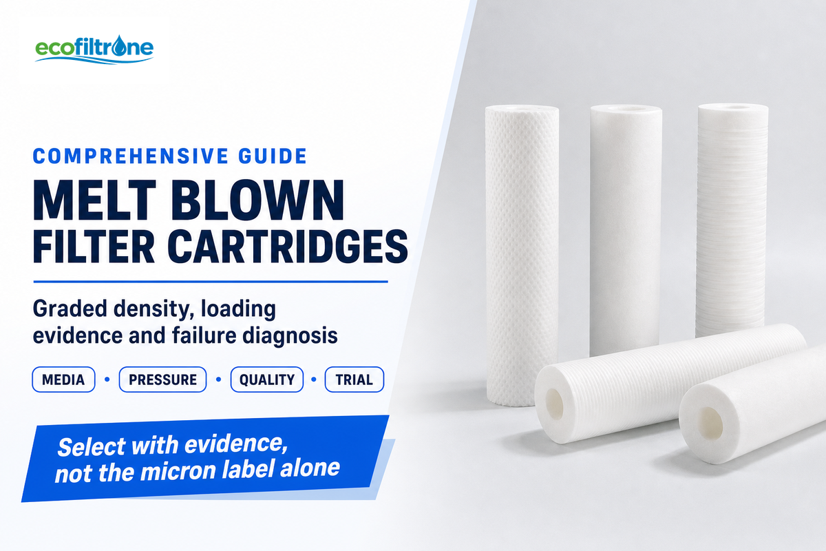
Technical guide · Depth filtration · Operating diagnosis
The description of a Melt blown filter cartridge is rather straightforward, and yet often misjudged. The usual shorthand—polypropylene, depth filtration, a stated micron rating—does not tell you how the element will load in your liquid, what a rising differential pressure means, or why two apparently similar cartridges may reach different changeout points.
This guide covers different ground. It links theory and field observations to show how short runs are diagnosed before changing the specification or supplier. For available configurations and commercial details, use the ECOFILTRONE™ melt blown filter cartridges page.
What Melt Blown Filter Cartridges Actually Do
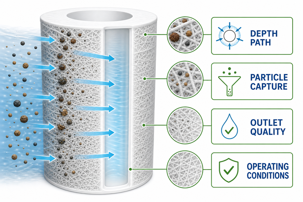
A melt-blown cartridge is a porous cylinder of polypropylene fibers, through which liquid flows and particles encounter capture sites inside the wall.
That distinction matters operationally. A given melt-blown cartridge can retain particles while restriction changes gradually, but the result depends on the quality of the fluid and other process variables, as well as the media structure and the intended quality of the outlet. A sediment filter cartridge used in water filtration therefore can’t be selected by “5 micron” alone. If you need the terminology behind nominal and absolute ratings, read the separate filter micron rating guide; this article stays focused on loading and diagnosis.
How Melt-Blown Media Is Formed and Why Density Changes Through the Wall
Melt blowing produces a bonded fiber network as opposed to a drilled array of identical openings. The production process can modify fiber diameter and deposition as the wall grows, allowing the pore structure to vary through the cartridge without implying a universal layer count.
Those construction differences are real; universal conclusions about service life, dirt capacity or total cost are not.
The resulting fibers are collected and bonded into a porous structure. Factors such as die geometry, polymer, air conditions and collection affect fiber formation, as described in North Carolina State University technical literature.1 A tubular cartridge adapts this principle by depositing a fiber web around a cylindrical collector.
During the deposition of the fiber network, characteristics can be modified. That makes a pore and density gradient possible, but it does not mean every product contains the same number of discrete layers. US5733581A describes apparatus for making melt-blown filtration media with integral particle-size gradation. A published patent describes an apparatus for producing melt-blown media with integral particle-size gradation; it is evidence of a disclosed mechanism, not proof that every commercial cartridge behaves identically. 2
Fiber Deposition Can Create a Pore Gradient
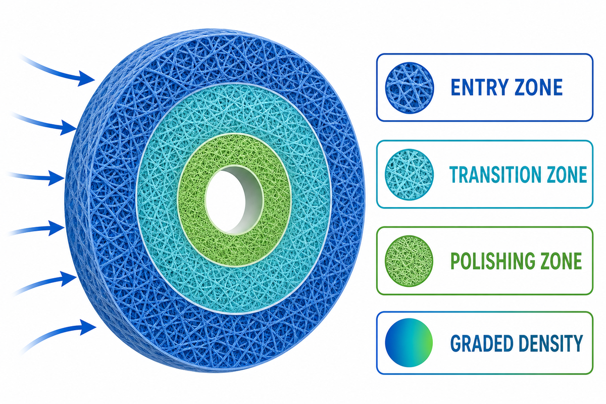
The Three-Zone Depth Capture Model
It is useful to picture the cartridge wall as three functional zones. These are an explanatory model, not a guaranteed layer count.
1. Entry zone
A relatively open outer region admits the liquid and intercepts part of the coarser load. If this zone blinds immediately, the feed may contain more large or deformable material than the original selection assumed.
2. Transition zone
A progressively tighter fiber network provides additional capture sites. This is where distributed loading can use more of the wall instead of building a single surface cake.
3. Polishing zone
The finer inner region supports the final retention duty. Its result still depends on the product’s stated efficiency, test basis and operating conditions.
Donaldson describes a graded-density product matrix with lower density at the surface and higher density toward the core.3 That supports the direction of the model. It doesn’t justify copying that supplier’s performance claims onto another cartridge or another process.
A density gradient can change where larger particles and finer particles load within the wall, creating an effective depth rather than one flat capture plane. This by itself doesn’t necessarily imply a higher filtration efficiency or total removal. The assessment will largely hinge on the complete medium, particles of different sizes in the challenge, operating condition and the stated test method.
Read Differential Pressure and Filtrate Quality Together
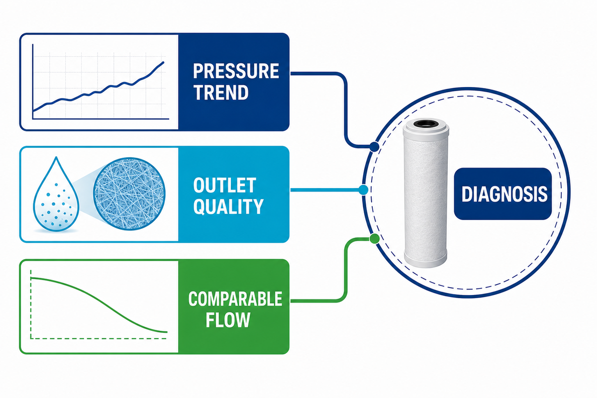
Pressure and quality answer different questions: one tracks hydraulic restriction, while the other tracks the required process result. Reading both under comparable operating conditions narrows the diagnosis without pretending that two signals alone identify every loading or bypass mechanism.
What does a rising differential pressure mean?
Differential pressure, across a cartridge element, indicates element restriction. Filtrate quality, measured by parameters of interest to the process, such as particle counts or turbidity, indicates the process result.
Choose the quality metric that matches the process objective: for example, size-resolved particle count, turbidity, or a specific contaminant assay. These measurements can’t be substituted for one another. Stable turbidity does not prove control of an unmeasured contaminant, and paired pressure-quality trends support diagnosis rather than prove a particular removal claim.
Neither signal is sufficient by itself. Pressure comparisons also need comparable flow, temperature and viscosity. A colder or more viscous liquid can create a higher pressure drop without a proportional increase in retained solids.
The Pressure, Clarity Loading Map
| Observed pattern | Likely interpretation | First checks |
|---|---|---|
| Stable differential pressure; stable outlet quality | The run may still be in its useful baseline region. | Confirm instruments, flow and sampling frequency; keep trending cumulative throughput. |
| Rising differential pressure; stable outlet quality | The cartridge may be loading normally, or it may be blinding faster than expected. | Normalize for flow and viscosity; compare feed solids, gels, oils and upstream protection. |
| Stable differential pressure; degrading outlet quality | Restriction is not increasing as expected while retention worsens. | Check sealing, seating, bypass routes, damaged media and the suitability of the stated rating. |
| Rising differential pressure; degrading outlet quality | The element may be overloaded, deformed, bypassing under stress, or facing a changed feed. | Protect the process, inspect the spent cartridge and housing, and review the event timeline. |
The map is a diagnostic organizer, not a remote diagnosis. A manufacturer troubleshooting article, for example, relates premature clogging to changes in pressure and process conditions upstream.4 You must determine the root cause from your run record.
Why can clear filtrate and low pressure still hide a problem?
A low reading can occur with bypass, poor seating, or quality change that the selected measurement can’t see. EPA cartridge-filter guidance similarly considers differential pressure and influent/effluent quality as paired operating evidence, and states that turbidity may not reveal all failures.8 Confirm the seal, sampling method and process-specific output instead of treating clear liquid as proof.
Diagnose Premature Changeout With an Evidence Ladder
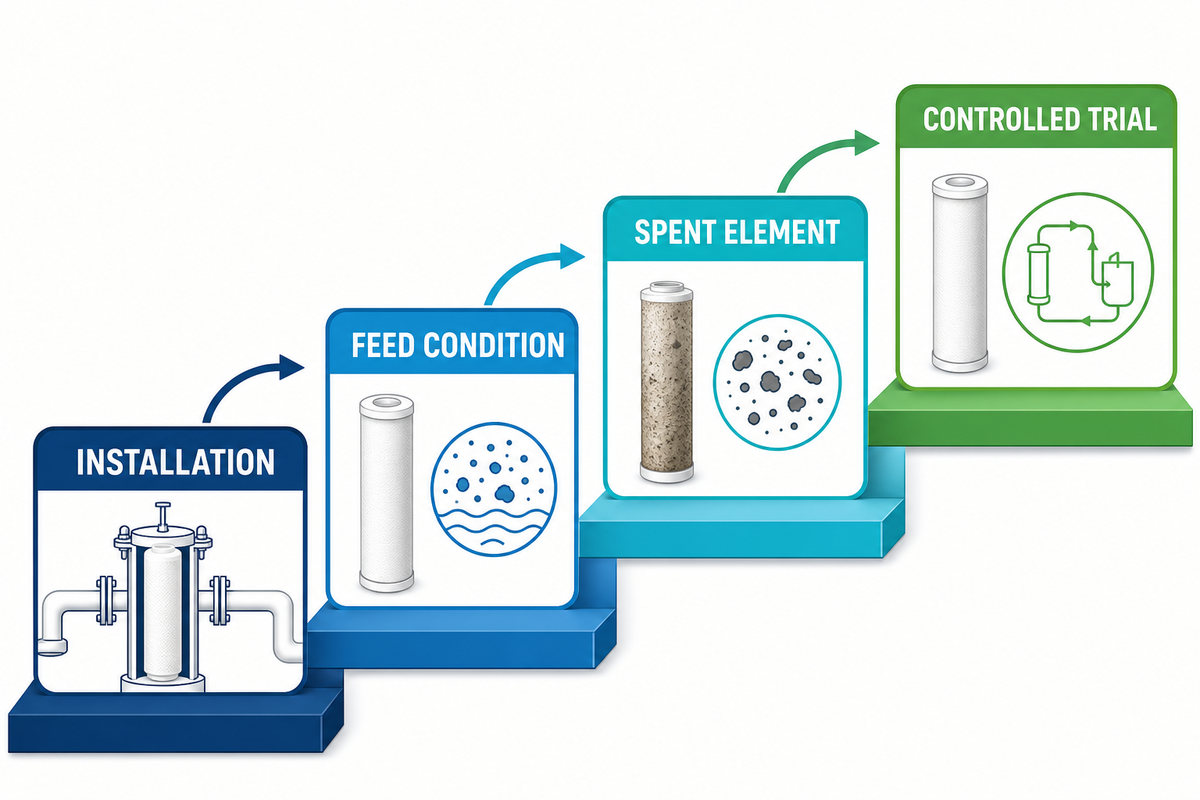
“Short service life” isn’t a failure mode. It is a comparison against an expectation, often without equal feed and operating conditions. Use the ladder alongside a manufacturer troubleshooting reference before attributing the problem to a supplier or cartridge lot.
Step 1: Verify instruments, valves, seals and installation
Review the position of check valves and cartridge seals. Also, evaluate the adapters and O-rings, housing closure, intended flow direction, and quality of seals and seating. A seal or seating problem can create a quality complaint without the pressure curve expected from normal media loading.
Step 2: Compare the feed and operating condition
Consider changes in suspended solids, distribution of particles, oils, gels, and biological growth. Also check for changes in batch chemistry or upstream cleaning. Then compare flow, temperature and viscosity. Plot differential pressure against cumulative volume. A faster production campaign can make an acceptable cartridge appear to have a shorter life when measured only in hours.
Step 3: Inspect the spent element
Take into account where material is accumulating, whether the wall is evenly loaded, if the element is deformed, if there’s evidence of channeling or bypass, part number, lot, and date of installation and in service history. Visual inspection is not a substitute for particle or quality data, but it helps connect the curve to a physical condition.
Step 4: Isolate specification or lot effects
Once the aforementioned variables are accounted for, you can compare different cartridge lots or specifications. Run candidates in the same housing with the same feed basis, instrumentation and endpoint. This makes “Brand A lasted longer” a traceable result.
When Melt-Blown Depth Media Fits, and When It Does Not
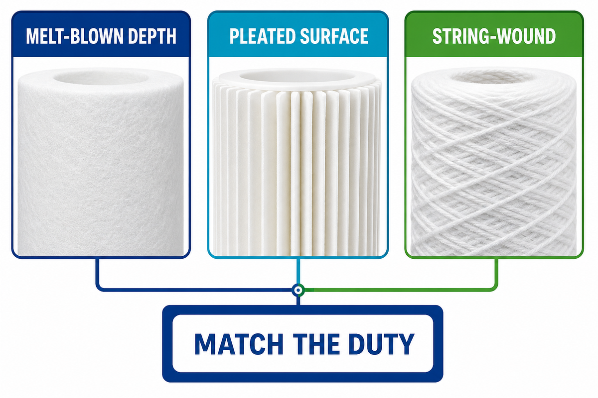
Melt-blown depth media is a viable option when the process allows for disposable depth capture, compatibility with the polymer and distributed loading. Across liquid filtration duties, it may serve as pre-filtration for reverse osmosis, clarification in water treatment or wastewater, and particulate control in chemical industry and electronics industry production processes. Each use still needs its own compatibility and quality endpoint.
Folded media in Pleated cartridges gives more surface area in a given envelope. String-wound cartridges create a different depth path through yarn wound around a core. Those construction differences are real; universal conclusions about service life, dirt capacity or total cost are not. A comparison article may say that one architecture generally lasts longer, but such a claim cannot be transferred to a different feed, flow and endpoint without a trial.
Use architecture to form a hypothesis:
- Consider melt-blown depth media when distributed loading and a disposable bonded matrix match the contaminant and compatibility requirements.
- Evaluate pleated media when available surface area, a specific retention construction or cleanability is important. Available surface area, a specific retention construction and cleanability are factors to consider when evaluating whether pleated media fits the process. See the existing PP pleated filter cartridge guide.
- Evaluate string-wound media where its material, winding structure and operating behavior suit the duty.
Then test the hypothesis. Dirt-holding capacity and consistent performance are measured outcomes, not automatic features of a graded wall. Actual cartridge life depends heavily on usage and environment; graded construction does not guarantee a longer run in every process. 5
Industry labels such as melt blown sediment filter and wire wound refer to construction families and not a complete filtration solution. The medium must effectively capture the relevant solids without exceeding the process pressure allowable. High dirt-holding capacity claims need the same controlled operating conditions as any purification result.
Build a Controlled Validation Trial Before Changing the Specification
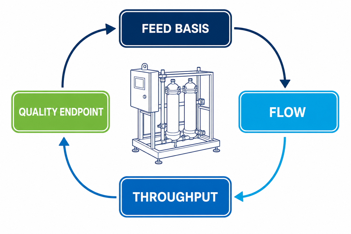
A good starting point for a trial is a data card. Without it, the team may compare cartridges that saw different feed loads or were removed for different reasons.
What data belongs on the trial card?
| Field | What to record | Why it matters |
|---|---|---|
| Run identity | Date, operator, candidate code, lot and installation position | Keeps every reading attached to the tested assembly. |
| Process fluid | Identity, composition, pH and relevant compatibility concerns | Confirms material suitability and bounds the comparison. |
| Feed condition | Particle or solids measure, relevant size distribution and shape, visible events, batch and upstream-stage status | Prevents a different or dirtier challenge from being blamed on the cartridge. |
| Operating condition | Flow, temperature, viscosity or a defensible proxy | Makes differential-pressure curves comparable. |
| Pressure | Upstream, downstream and calculated differential pressure at defined intervals | Shows restriction and its rate of change. |
| Outlet quality | The process-relevant measure, method, reporting or detection limit, sampling point and frequency; define whether initial, mid-run and endpoint samples are needed | Shows whether the filtration objective is being met across the intended run. |
| Throughput | Cumulative volume or batch mass at each reading | Separates production rate from useful processed capacity. |
| Hardware | Housing, cartridge length, adapter, seal, quantity and installed lot | Controls interface and installation differences. |
| Endpoint | Validated system limit, quality failure, planned batch end or another agreed rule | Ensures every candidate is judged on the same basis. |
Flow deserves special attention because it influences resistance and capacity interpretation. Technical trial guidance emphasizes defining flow when testing filter performance. 6 Do not borrow a universal changeout pressure from an unrelated installation; use the validated limit for the element, housing and process.
Which endpoints make two runs comparable?
State what the result means, be it one cartridge, a product family or a complete housing and cartridge assembly. Not every installation requires a new regulatory challenge test, but an operational comparison still needs controlled conditions and an output measure aligned with the actual process requirement.
For filtering liquids, define the endpoint before the run. This may be a validated pressure limit, a process-relevant quality limit, or an agreed batch boundary. A pure-water application may use a different output measure from other industrial processes, and no generic promise of efficient filtration can replace that declared measure.
Decision Framework: Keep, Adjust, or Re-Specify the Cartridge
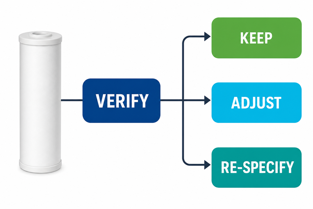
- Verify the evidence. Confirm pressure instruments, sampling method, flow and run history.
- Correct installation or operating drift. Address seals, seating, valve position, temperature, viscosity, and abnormal flow.
- Restore the feed basis. Investigate process events that occurred upstream, changes in process solids, and lost pre-filtration.
- Run an equal-condition comparison. Use the Controlled Trial Data Card, and define a common endpoint.
- Decide. Keep the cartridge if it meets the objective; adjust geometry or rating if the evidence supports it; re-specify media architecture when the contaminant and operating window demand a different capture mechanism.
This sequence applies the evidence checks described in EPA cartridge-filter guidance and protects against two mistakes: replacing a capable cartridge to fix a process issue or keeping an unsuitable cartridge because its label appears correct.
Frequently Asked Questions
Are melt-blown cartridges nominal or absolute rated?
They can be sold with nominal or absolute claims, depending on the product. The useful question is what efficiency the rating represents and under which test conditions. One published application example shows nominal 0.2 µm filters described with different efficiencies, illustrating why the label alone is incomplete.7 An NSF protocol or certification claim must be checked against its stated scope; use the supplier’s test basis and validate the result in the intended process, because an unqualified micron label remains incomplete purchasing evidence.
What causes a melt-blown filter cartridge to plug too quickly?
Possible causes include a higher sediment or solids load, gels or oils, colder and more viscous fluid, excessive flow, undersized filtration area, loss of upstream protection, or a pore structure poorly matched to the contaminant. A pressure curve by itself won’t identify the most likely reason. Compare feed, flow, temperature, cumulative throughput and outlet quality under equivalent conditions. Examine the installation and spent element.
How should differential pressure be used for cartridge changeout?
Trend pressure immediately upstream and downstream of the cartridge stage at comparable flow and fluid condition. Use the validated end point for the cartridge, housing and process; there’s no universal, responsible value for all cases. Also track outlet quality and cumulative throughput, and base changeout decisions on both mechanical integrity and the filtration objective. A changeout decision should protect both mechanical integrity and the filtration objective.
Are melt-blown cartridges better than pleated cartridges?
Neither architecture is inherently better. Melt-blown media has a bonded depth structure; pleated media has a folded surface area and can use multiple retention structures. The better choice depends on the distribution of the contaminants, the required outlet quality, the pressure limits, compatibility, cleanability and the trial endpoint. Compare them on the basis of the same conditions.
What information should be sent to a cartridge supplier?
Send the process fluid and compatibility constraints, contaminant evidence, required outlet quality, flow, temperature, viscosity, housing interface, clean and terminal pressure data, current failure pattern and a proposed trial endpoint. State which filtration needs are measured, estimated or unknown. This gives the supplier a basis to recommend a configuration. A micron label may answer part of the problem but not the whole.
Match the Evidence to a Commercial Configuration
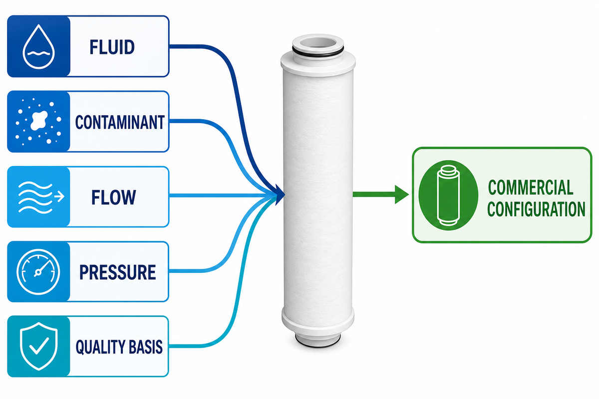
Review the available melt blown filter cartridge configurations once you have the fluid, contaminant, flow, pressure and quality basis. ECOFILTRONE™ can use that evidence to discuss a sample or matched specification without duplicating the diagnostic work.
The same evidence-first method applies whether the cartridge protects industrial water systems or another liquid process; the objective is not to force one melt-blown sediment format into every duty.
For company background and manufacturing context, see About ECOFILTRONE™.
References & Sources
- North Carolina State University: Overview and Analysis of the Meltblown Process and Parameters is available at North Carolina State University: Overview and Analysis of the Meltblown Process and Parameters
- US5733581A: Apparatus for making melt-blown filtration media having integral particle-size gradation.
- Donaldson: PP Meltblown Liquid Filter Cartridges.
- Donaldson: Filtration troubleshooting and trap-filter failures.
- All filters: Cartridge life depends on usage and environment is available at All Filters: Cartridge life depends on usage and environment.
- To learn about flow rate and filter testing, see BioPharm International: When flow rate matters in filter testing.
- Critical Process Filtration: Nominally rated depth filters are not all equal.
- U.S. EPA: LT2ESWTR Toolbox Guidance Manual, cartridge-filter monitoring.
- Ulster University: cartridge-filter pressure, capacity and turbidity study.
Filtration selection brief
Bring the operating details that shape the next conversation
Record what is known from the line or process. A complete specification is not required to start.
Useful inputs
- Fluid and processFluid name, process stage, and any compatibility concern.
- Filtration targetRequired result, existing rating, or the issue to solve.
- Flow and run timeTypical flow range, batch size, or expected service interval.
- Installation conditionsHousing or connection details, temperature, pressure, and available space.
Next step
Send the details you have
Use the inquiry form to start a focused discussion and add drawings or photos when they help explain the installation.
Start an inquiry