Get in touch with ECOFILTRONE™ Company



Updated October 2026
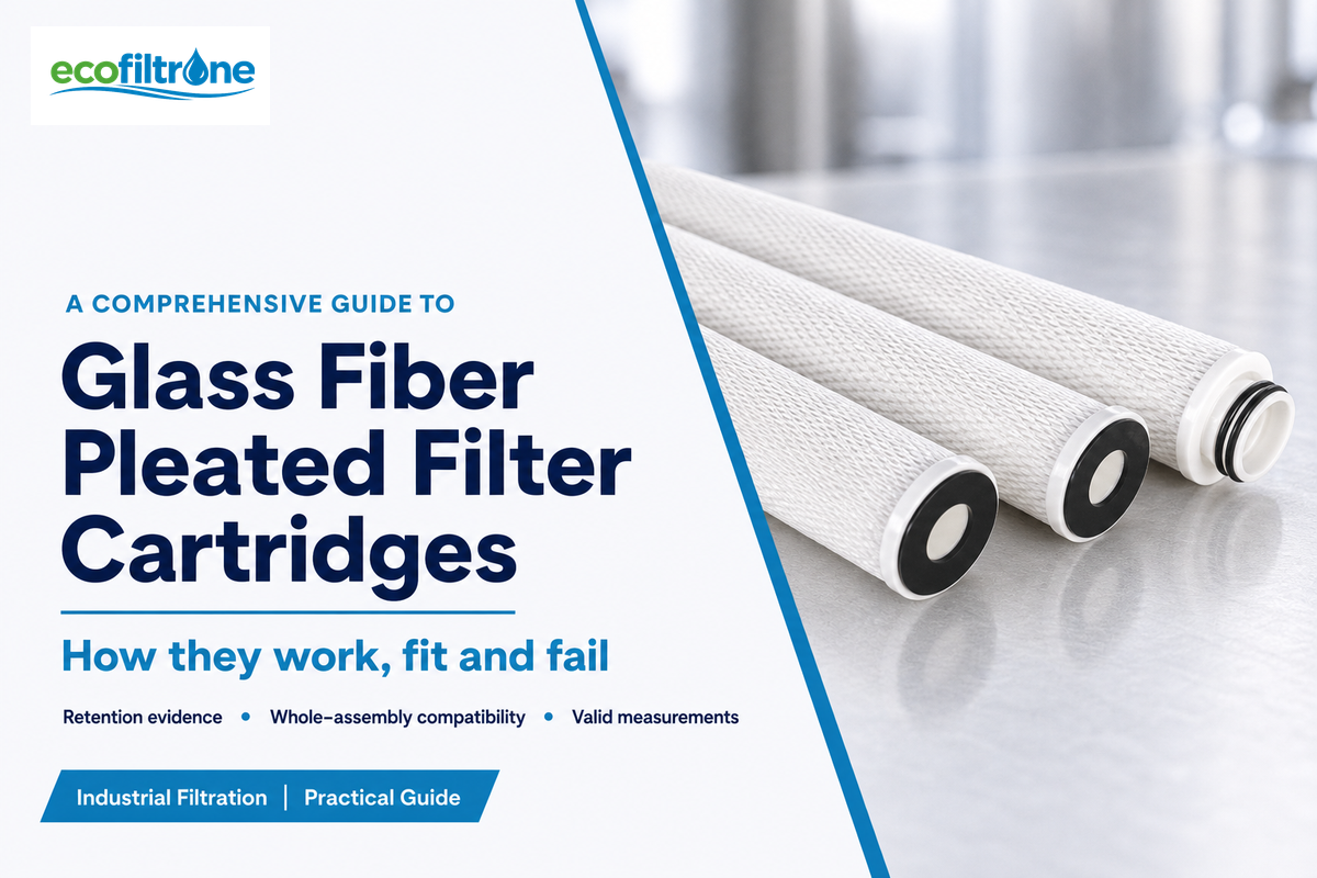
Glass Fiber Pleated Filter Cartridges incorporate a fibrous filtration medium and a folded cartridge format. While the particles should always be the first consideration, the entire wetted construction and evidence supporting the rating also need to be taken into account; price and cleaner-looking liquid cannot settle those questions.
Glass Fiber Pleated Filter Cartridges use folded glass-fiber media for particle filtration. Removal performance depends on the particular media and test conditions. Check retention evidence, fluid compatibility and assembly limits before choosing a cartridge for industrial liquid service.
Key points before comparing cartridges
- Pleating describes the shape. Even folded media can capture particles through their thickness.
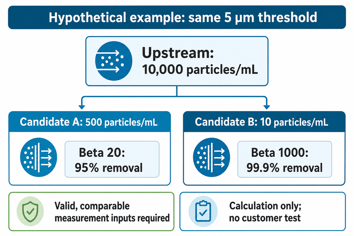
- For an identical particle threshold, β20 indicates 95% removal and β1000 indicates 99.9% removal.
- Pressure and particle results answer different questions. Confirm the measurements before diagnosing a filter.
- In the review of compatibility, consider binders, supports, end caps and seals.
Quick reference: what each specification means
| Reported item | What to request |
|---|---|
| Micron rating, µm | Particle threshold, removal efficiency and challenge method |
| Flow, L/min or m³/h | Fluid, temperature, viscosity and associated pressure drop |
| Temperature, °C | Continuous operating conditions separately from sanitation conditions |
| Differential pressure, bar or kPa | Forward/reverse limit and the approved replacement criterion |
| Materials | Medium, binder, support layers, core, cage, end caps and seals |
This is a reading guide; a universal product specification isn’t included. For the exact cartridge configuration, review the current datasheet.
Glass Fiber, Pleats and Depth Capture: Three Different Properties
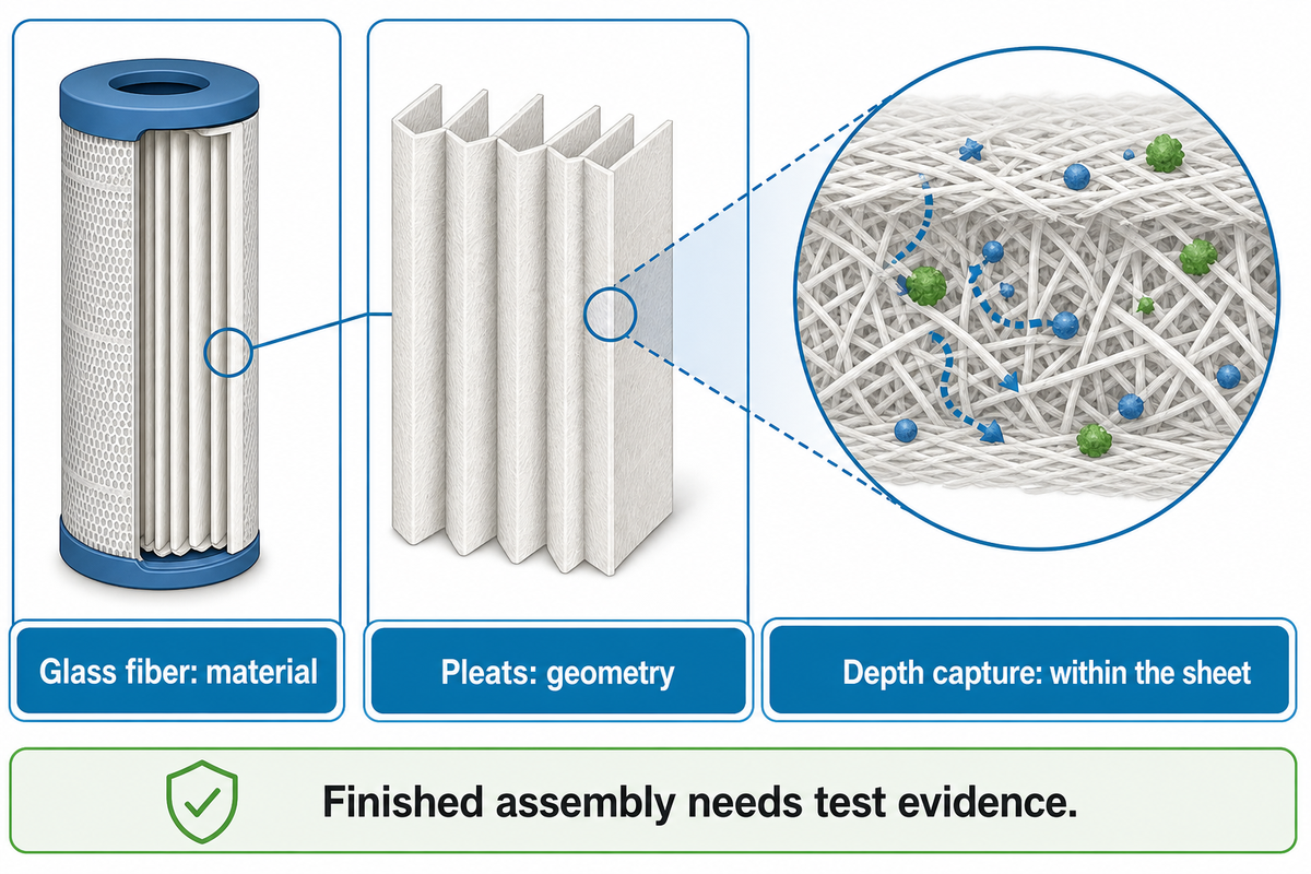
Glass fiber names the material, pleats describe the geometry and depth capture describes where particles are retained. Those properties can coexist in pleated cartridge filters. Folding a fibrous sheet increases the installed media area, but the finished construction and test results determine the useful performance in a given liquid.
How Is Glass Fiber Used in Filter Cartridges?
Fine glass microfiber can form a porous sheet supported inside a cartridge. Surface filters emphasize capture on an upstream barrier; a fibrous depth medium can retain particles within the sheet. Supports help the pack retain its shape, while the core, cage and end connections complete the assembly. When a datasheet specifies glass fibre media, ask if the sheet is the only thing described or the complete cartridge filter assembly.
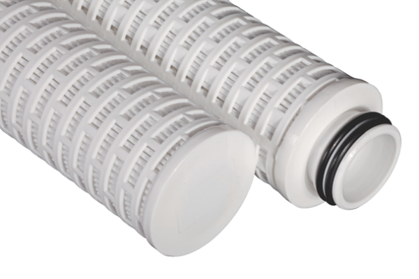
The EPA’s membrane-filtration manual also mentions pleating membrane and support layers to increase cartridge area. Their example of drinking water membrane shows why pleating is shared by pleated cartridge families; it doesn’t provide a glass-fiber cartridge rating.
Common mistake: treating every fiberglass filter as the same device. Liquid glass fibre cartridges and building air-filter panels have different construction and qualification requirements. An HVAC comparison cannot approve a cartridge for solvent, beverage or process-water service.
Chemistry of the materials is also important. Weiter and colleagues’ 2024 glass-fiber study found different separation behavior after surface treatment in spite of similar mean flow pore sizes. The study tested flat media in hydraulic oil and the authors included HYDAC employees. It suggests an approach to evaluate cartridge performance rather than to make a performance claim.
To show that a cartridge meets a 5 µm requirement, something other than pictures of pleats, or the word borosilicate, is required. For retention claims, evidence of particle removal should be shown. Request descriptions of the medium and support along with the test basis; evaluate cartridges under intended fluid conditions.
What Glass Fiber Filter Cartridges Can and Cannot Remove
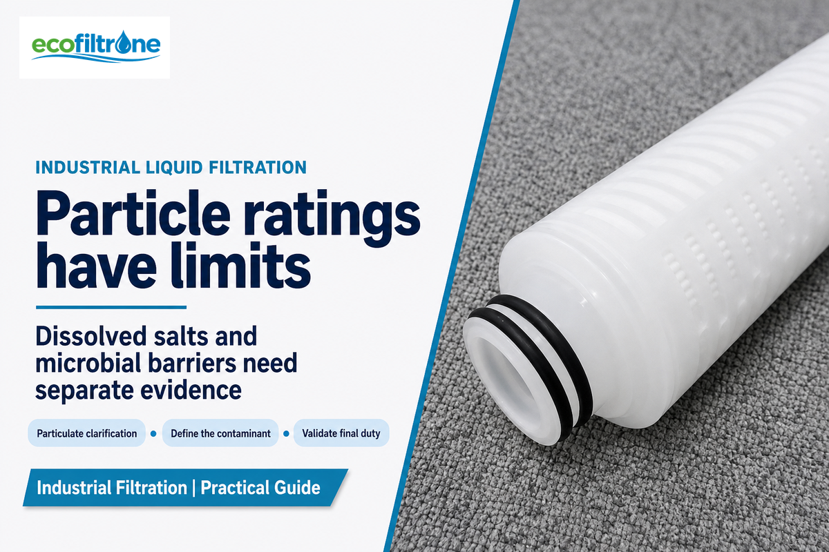
Glass-fiber cartridges may be considered for particulate clarification and prefiltration, if their material and retention considerations support the liquid. Particle ratings don’t confirm the removal of dissolved salts or a validated microbial barrier. Define the target contaminant and downstream quality requirement before selecting filtration.
What are glass fiber filters used for?
Removing suspended contaminations from a process liquid and providing pre-filtration for the next stage are industrial uses. Water treatment and chemical processing, and beverage clarification impose different acceptance criteria. Selecting a glass fiber filter cartridge for the removal of suspended solids doesn’t automatically qualify it for product recovery, fine colloids or final membrane duty.
- Match the size distribution of suspended solids and the acceptable downstream concentration for suspended solids removal.
- For dissolved species, identify the required separation mechanism. A particulate cartridge isn’t a desalination stage.
- Microbial control: Obtain application-specific validation for the exact final filter.
- Valued ingredients: Include recovery and composition checks for capture or adsorption when removal of a valued ingredient is a concern.
Refer to the University of Georgia guidance for information about distinguishing soluble reduced iron from the insoluble precipitate formed after oxidation. While the guidance is for private water system information, the distinction illustrates why a cartridge can’t be chosen from an iron-concentration result without knowing the form of the iron.
Analytical boundary: Novak and colleagues’ laboratory research found that dissolved organic carbon adsorbed on glass-fiber discs could enter the measured particulate-carbon fraction. That result concerns analytical discs, not industrial cartridge adsorption capacity. Include appropriate blanks when the measurement method uses a filter to define the particulate fraction.
Specifying 5 µm particle removal doesn’t ensure the removal of dissolved salts or the recovery of useful ingredients or the attainment of final microbial control. Prior to a media trial, identify the fraction that needs to be targeted and the analytical method that would best determine if a separation has occurred. In the absence of evidence for the other required outcomes, the media shouldn’t be considered acceptable on clearer appearance alone.
Micron Ratings and Beta Ratios: Compare What Gets Through
Two cartridges that are marked with the same micron rating can have different removal efficiencies or be based on a different test principle. The size-specific beta ratio compares the concentration of particles upstream and downstream. The ratio should be converted to filtration efficiency. Then consider the fluid, the challenge material, the loading state and the method of analysis to determine if the results are comparable.
Nominal and absolute ratings require the supplier’s interpretation. Neither term captures the full testing situation. Mean pore sizes are different from a demonstrated particle removal curve. The expression fine filtration requires the same interpretation of threshold, efficiency and test method. Specify the threshold as “particles at or above x µm,” with the laboratory’s sizing convention, rather than considering x as the beta value.
2-Count Pass-Through Comparison
A size-specific calculation to determine removal ratio based on matched upstream and downstream concentrations; permissible measurement inputs are required.
βx = Cupstream,x ÷ Cdownstream,x
Removal efficiency = (1 − 1/βx) × 100%
Use the same size threshold and specify concentrations in the same units. Purdue’s capture-efficiency explanation gives this relationship in an engine-oil example. This relationship is based on matched concentrations and doesn’t qualify a process-water cartridge from the original engine-oil example.
| β for an identical 5 µm threshold | Upstream concentration | Calculated downstream concentration | Removal efficiency |
|---|---|---|---|
| 2 | 10,000 particles/mL | 5,000 particles/mL | 50% |
| 10 | 10,000 particles/mL | 1,000 particles/mL | 90% |
| 20 | 10,000 particles/mL | 500 particles/mL | 95% |
| 50 | 10,000 particles/mL | 200 particles/mL | 98% |
| 100 | 10,000 particles/mL | 100 particles/mL | 99% |
| 200 | 10,000 particles/mL | 50 particles/mL | 99.5% |
| 1,000 | 10,000 particles/mL | 10 particles/mL | 99.9% |
| 2,000 | 10,000 particles/mL | 5 particles/mL | 99.95% |
| 5,000 | 10,000 particles/mL | 2 particles/mL | 99.98% |
For a hypothetical case, quality staff found 10,000 particles/mL upstream and 500 particles/mL post cartridge for the same 5 µm threshold. Dividing 10,000 by 500 gives β 5 = 20 and 95% removal is given by (1-1/20) × 100. Under the same circumstances, a second candidate with 10 particles/mL gives β5 = 1000 and 99.9% removal. There’s a considerable difference, although both labels may include “5 micron.” Purchasing should request the test basis before treating them as interchangeable. Equal sample-volume normalization is the minimum requirement; calibration, sampling losses and counting limits also have to be acceptable. These examples show the calculations and give no customer test examples, nor set an acceptance level.
NIST’s particle-concentration research examines timing and coincidence errors, measured-volume calibration and losses to tubing or cell walls. Correct calculations can’t compensate for biased inputs. As a reporting precaution, below the validated counting range, request the laboratory’s reporting limit; don’t present a zero or uncertain downstream count as proof of complete particle removal.
The public scope of ISO 16889:2022 is hydraulic-fluid multipass testing. ISO 11171:2022 addresses automatic-counter calibration in hydraulic and other petroleum-based fluids. Ask what method applies to your liquid; citing either standard does not establish universal process-water compliance.
With 10,000 particles/mL upstream, β20 leaves 500 particles/mL, and β1000 leaves 10 particles/mL for the same threshold. Require equivalent test conditions and valid measurements for substitution decisions. Compare the measurement basis, efficiency and size of the particles before accepting the replacement as equivalent protection.
Glass Fiber vs Polypropylene vs Membrane: Match the Duty
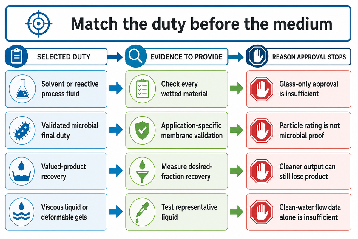
A media comparison that holds separation and operating conditions constant is useful. Glass fiber, polypropylene and membrane constructions provide different candidates, but the material name doesn’t establish a universal winner. Evaluate the option that addresses the limiting duty without losing required retention and ingredient recovery or compatibility with the complete assembly.
Of the candidates available, useful filtration area depends on accessible flow paths and loading behavior. Claims of high dirt-holding capacity and longer service life require a stated challenge and endpoint. Low pressure drop measured with clean water also can’t establish throughput in a viscous liquid containing deformable contamination.
| Duty type | Candidate to investigate | Deciding evidence | Reason to stop approval |
|---|---|---|---|
| Suspended fine-particle clarification | Rated glass-fiber or PP pleated media | Comparable efficiency curve and filtrate result | Same micron label, different removal basis |
| Broad incoming size distribution | Depth medium or staged arrangement | Feed distribution, useful volume and available pressure | Staging exceeds operating headroom |
| Viscous liquid or deformable gels | Construction tested with representative liquid | Flow/pressure behavior and loading test | Only clean-water flow data available |
| Solvent or reactive process fluid | Compatible complete cartridge assembly | Every wetted material at operating conditions | Approval covers glass alone |
| Final particle-control duty | Candidate meeting the specified retention method | Final-stage acceptance and test traceability | Prefilter evidence substituted for final duty |
| Validated microbial final duty | Specifically validated membrane product | Application-specific validation | Particle rating offered as microbial proof |
| RO protection | Prefilter suited to documented feed conditions | Feed characterization and downstream requirements | Cartridge change leaves upstream cause unresolved |
| Valued-product recovery | Medium tested for desired-fraction recovery | Product balance and non-target adsorption | Cleaner filtrate accompanies unacceptable product loss |
| Repeated sanitation exposure | Assembly with documented permitted procedure | Exposure conditions and retained performance | Operating temperature mistaken for cleaning approval |
Consider a hypothetical beverage clarification trial with two compatible candidates. Operations prefers the cartridge which maintains the required flow for a longer cycle. Quality staff find the apparently clearer output also contains less of a desired component. The candidate therefore fails the agreed product-recovery condition, even if its differential pressure is lower. Only candidates satisfying particle control and composition requirements are compared for costs. The next trial holds feed batch, sampling locations and flow constant, while adding an appropriate recovery measurement. No medium wins from appearance alone. A glass fiber pleated filter can be a candidate. Efficient filtration, including preserving the product that the process is intended to make, is preferred.
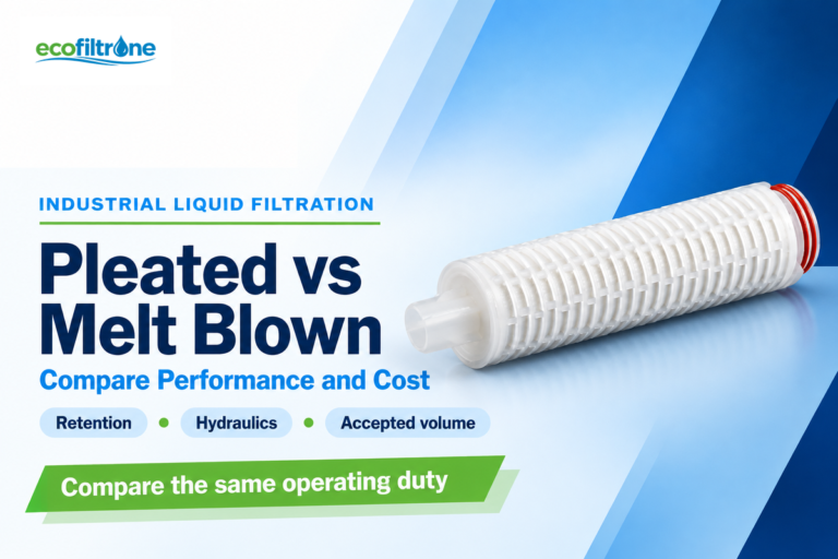
See polypropylene pleated media when its verified assembly and retention suit the duty. Consider melt-blown depth filtration for broad particle distributions for depth constructions. Tim Sheehan’s historical bag-versus-cartridge discussion illustrates application constraints. It gives no current price or universal capacity advantage.
Candidates labeled 5 µm need equal removal evidence before longer cycles of theirs can be considered an improvement. Maintain fluid and quality constant and assess useful throughput and wanted product recovery. A less expensive or high-flow cartridge that misses either requirement creates replacement work without meeting the process duty.
Chemical Compatibility Belongs to the Whole Cartridge
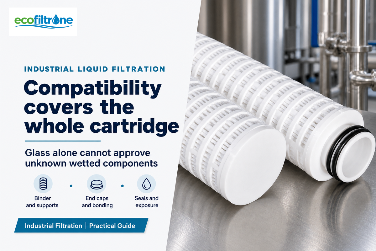
Chemical compatibility belongs to the complete wetted assembly that’s exposed to the intended service conditions. Resistance of glass fiber alone isn’t sufficient to approve a cartridge containing other materials. Evaluate the medium, binder, and support structures, and the seals, then assess the operating liquid and permitted sanitation procedure.
Binder may be present in the medium even with cartridge joints thermally bonded. If a supplier describes polypropylene filtration layers or polyester supports, consider each layer’s role and wetted exposure. Request the actual material declaration, as construction varies from product to product. Obtain the construction declaration for the actual part, rather than assuming it from a “GF pleated” description.
Assembly review: check medium → binder → support layers → core and cage → end caps and bonding → seals. Missing material declarations leave an open compatibility question. “Excellent chemical compatibility” without a fluid, concentration and temperature is insufficient approval evidence.
ISO 2943:1998’s public compatibility-test scope provides a useful boundary: the hydraulic filter-element mounting seal is excluded. Therefore, test reports to this method don’t validate the seal. Ask which parts and exposures the evidence covers; the hydraulic standard is not a universal industrial-liquid requirement.
- Describe the process fluid and what it’s mixed with, including concentration and normal temperature.
- Identify temporary exposure during startup, shutdown or approved cleaning.
- Request forward/reverse pressure limits at the relevant temperature.
- Distinguish descriptions of bonds or welds from evidence of extractables, fiber migration and product compatibility.
Processes at 60°C require evidence for the actual assembled cartridge at that exposure; the example temperature isn’t a permitted limit. Glass fiber membrane labels and high-strength cages don’t approve unknown seals. Request a component-specific review before substituting materials or planning a cleaning cycle.
Flow, Viscosity and Differential Pressure: Keep the Limits Separate
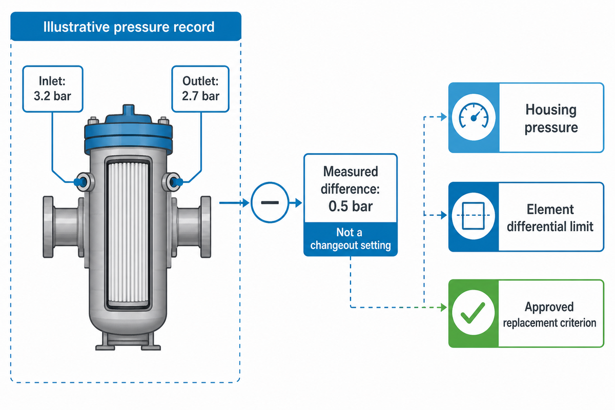
Differential pressure is the difference in pressure between two points in a given flow system. It can be affected by frictional pressure loss in the system and other variables. Keep housing operating pressure, element differential pressure limits, and element changeout criteria separate. None can be determined from the others or from the phrase low pressure drop.
| Measurement or limit | Meaning | Practical check |
|---|---|---|
| Inlet and outlet pressure, bar | Pressures at the chosen measurement ports | Record both under identical operating conditions |
| Measured ΔP, bar | Inlet minus outlet across those points | Confirm whether the ports include housing losses |
| Element differential limit | Documented limit for direction and temperature | Use the exact configuration’s specification |
| Routine replacement criterion | Approved operating or quality endpoint | Do not replace it with the structural maximum |
For an illustrative record, 3.2 bar inlet minus 2.7 bar outlet gives 0.5 bar across the measurement points. Those readings describe that operating condition; 0.5 bar isn’t a recommended changeout setting. If flow or liquid temperature changes, compare with a baseline recorded at equivalent conditions before attributing the difference to loading.
High flow increases the importance of having a flow curve that’s aligned with the fluid, while high temperatures, cold starts and variations in fluid viscosity can alter hydraulic behavior. Supporting this, statements of high-performance cartridges require review of the appropriate flow curve and operating envelope, including the housing and number of elements installed.
Reading boundary: Edward Sylvester Jr.’s RO monitoring article distinguishes observations across pretreatment and RO stages. RO-stage pressure and cleaning criteria must not become cartridge changeout thresholds.
Troubleshooting: When Pressure and Particle Results Disagree
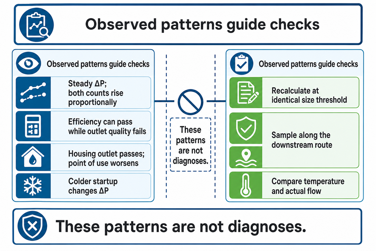
There can be differences between observed pressures and particle results, because they’re measuring different parts of the filtration problem. First verify the operating point and measurement chain, then compare feed, immediate outlet and downstream samples. The observed pattern helps narrow the possible causes; it doesn’t prove bypass, fiber migration or a damaged cartridge.
Pressure, Particle Divergence Map
This competing-cause map separates questions of measurement, loading, assembly and downstream contamination before attributing a failure to a cartridge.
| Observed pattern | Possible explanation | Next discriminating check | Decision boundary |
|---|---|---|---|
| ΔP rises; outlet result remains acceptable | Increasing restriction or different duty | Match flow/temperature and inspect feed loading | Use approved endpoint, not the table as a setpoint |
| ΔP steady; upstream and outlet counts rise proportionally | Dirtier incoming liquid with unchanged ratio | Recalculate at identical size threshold | Acceptable efficiency can coexist with unacceptable outlet concentration |
| ΔP steady; upstream steady; outlet worsens | Retention, assembly or measurement change | Validate counts and check fit/seals under site procedures | No automatic fiber-migration diagnosis |
| Low ΔP; unexpectedly poor removal after replacement | Wrong element, seating, bypass or unlike rating | Check traceable part and installation records | Low resistance alone is not proof of filtration |
| Housing outlet acceptable; point of use worsens | Contamination introduced downstream | Sample along the downstream route | Replacing the cartridge may not address the source |
| Counts change with analyzer or sample handling | Different calibration, limits or sampling loss | Review method and appropriate blanks/controls | Incomparable data cannot approve a new cartridge |
| Apparent particles appear after chemistry changes | Precipitation or a changing analytical fraction | Check material form and analytical method | Do not equate all new counts with feed dirt |
| ΔP changes after a colder startup | Changed viscosity and hydraulic duty | Compare temperature and actual flow | Do not diagnose loading from unmatched conditions |
| Removal looks better; wanted-product recovery worsens | Non-target capture or adsorption | Measure the desired fraction and process balance | Particle improvement alone cannot pass the trial |
Suppose an illustrative RO-prefilter record shows 0.3 bar differential pressure under an identical 40 L/min duty on two checks. At the stated 5 µm threshold, upstream concentration increases from 1,000 to 10,000 particles/mL and the immediate outlet rises from 10 to 100 particles/mL. Both observations give β5 = 100, or 99% removal. The outlet is dirtier even though the calculated efficiency is unchanged. Quality staff still compare 100 particles/mL with the plant’s own acceptance requirement. Operations investigates the feed change rather than assuming a cartridge defect. Separate point-of-use samples can then establish whether additional contamination appears downstream. These hypothetical values teach pattern separation; they’re neither RO acceptance limits nor client operating records.
A Water Technology account of high-purity pretreatment shows that with upstream treatment and fouling by fine particles, downstream behavior can be altered. Its case study of a historical plant doesn’t predict the behavior of glass-fiber service life. Take a close look at your RO Pretreatment requirements when feed quality changes based on actual feed water and equipment conditions.
At 1,000 particles/mL in the upstream concentration and 10 particles/mL in the downstream concentration, beta is 100; increasing both concentrations tenfold leaves that ratio unchanged. The process can still fail to meet the outlet quality requirement. The principle is to keep concentration, efficiency, and pressure as separate observations. Validate the sample chain before deciding on a corrective action.
Evidence That Makes a Media Trial Comparable
Equivalent media trials fix the quality objective, operating condition and measuring method prior to assessing useful service. Operations records conditions, and quality staff determine whether the output and desired-product recovery meet the agreed requirements. Purchasing evaluates the cost of acceptable service only after addressing compatibility, physical fit and required filtration evidence.
“Accurate number concentrations of particles in liquid media are needed to assess the quality of water, pharmaceuticals, and other liquids”
Maintain the candidate’s documents and rating basis with the trial record. Match feed condition, flow and temperature; locate sample ports and use the counter method. To evaluate a hypothetical 40 L/min flow at 25°C, an observation at a different flow or fluid temperature may be used for comparison, but an explanation of the reason for the comparison is required.
- Operations: Operations records installed configuration, first pressure, changes in duty and permitted endpoints.
- Quality: Quality compares valid upstream/outlet measurements with specified limits, and adds blanks or recovery checks as appropriate.
- Purchasing: compare accepted useful volume, cartridge consumption, changeout work and documented replacement obligations.
- Joint decision: retain unresolved material, fit or measurement questions as reasons to defer approval.
Evaluate cost against accepted service, not calendar life alone. Cartridges with long service life that fail the product-quality target can’t be credited with that full cycle as useful filtration. Conversely, an early endpoint caused by a dirtier feed shouldn’t be compared with a cleaner feed in the previous batch.
Next step: use the evidence record to identify the exact configuration question. ECOFILTRONE™ supplies industrial filtration consumables with engineering support for selection and replacement matching. Its Glass Fiber Pleated Filter Cartridges solution page carries the product-selection handoff. Review other media families when the evidence points to a different medium.
Frequently Asked Questions
When should glass fiber pleated filter cartridges be changed?
Use the approved changeout criterion and confirmed quality results.
Change the cartridge at the product-specific changeout criterion or when confirmed filtrate quality no longer meets your process requirement, whichever comes first. Record flow, temperature and differential pressure together, because operating changes can alter the reading. The maximum element differential-pressure rating is a structural operating limit, not automatically the preferred routine replacement trigger.
Can glass fiber pleated filter cartridges be cleaned and reused?
Reuse requires approval for the particular cartridge and procedure.
Reuse requires an explicit procedure and acceptance criteria for the particular cartridge. Pleated geometry doesn’t prove that trapped particles can be removed from fibrous depth media without damage or a change in retention. Check the permitted cleaning chemistry, flow direction and verification method. Without documented approval, don’t treat rinsing as evidence that original filtration performance has returned.
How can you check the quality of a glass fiber cartridge?
Review traceable construction, retention evidence and application results.
Start with a traceable part description, complete materials of construction and documented particle-removal performance under a stated test method. Then confirm dimensions, end connections, seals and operating limits against your housing and process. Sample trials should also meet your agreed filtrate-quality criteria. Appearance, media name and a general company certificate don’t establish product suitability by themselves.
Are used glass fiber cartridges recyclable?
The complete assembly and captured material determine available disposal routes.
Used cartridges combine media, supports, seals and captured material. Those components may prevent ordinary recycling. Follow the site’s waste classification and the locally accepted route for that specific assembly and contamination. Don’t assume that a glass-containing cartridge is recyclable or nonhazardous.
Is a glass fiber cartridge always better than a polypropylene filter?
Compare the required duty and accepted useful service.
No. A compatible polypropylene cartridge can meet a duty that another glass-fiber construction can’t, and a documented glass-fiber candidate can be worth testing when the existing medium limits useful service. The comparison must preserve the required particle-removal basis, complete assembly compatibility and product-quality acceptance. For example, a candidate that passes more liquid before replacement hasn’t improved the process if it also passes too many target particles or retains a wanted ingredient. Check the flow conditions and incoming loading as well: a longer trial on cleaner feed doesn’t demonstrate a material advantage. Membrane filters remain necessary where the particular final separation requires their validated performance. Choose the candidate that meets the agreed output requirements at acceptable operating and replacement cost. General claims of high filtration performance or high-quality media can’t replace comparable evidence for the process being evaluated.
Does an absolute micron rating mean sterile filtration?
Particle ratings do not establish a microbial barrier.
No. Particle-removal ratings describe retention under a stated particle test. Validated microbial performance requires evidence for the exact product and application. Glass-fiber prefilters or bioburden reduction claims must not be treated as proof of sterilizing-grade final filtration.
Is low differential pressure proof that the filter is working?
Check the reading against operating conditions and filtrate quality.
Low differential pressure can reflect low resistance at the measured operating point, but it doesn’t prove adequate particle removal. Confirm flow, temperature, instrument condition and the actual installed element. Compare valid feed and outlet samples at the relevant threshold. Incorrect fit, an unintended bypass path, changing feed or downstream contamination are possibilities to investigate, not conclusions that follow from a low reading alone.
Bring the unresolved duty to a configuration review
Share your fluid, particle target, operating conditions, part, and questions left unanswered by your comparison. ECOFILTRONE™ can verify selection and replacement requirements prior to you customizing a cartridge configuration.
This guide integrates published, publicly available technical information, and specifically identifies hypothetical examples of calculations and trial-based evaluations. It discloses no evidence of proprietary plant testing. Product documents, material declarations and any compliance certificates should be reviewed to confirm the exact configuration and the actual certificate holder. The guide is limited to industrial liquid filtration; gas and compressed air require their own service qualification.
References & Sources
- EPA, Membrane Filtration Guidance Manual, sections 2.2.4 and 2.3.2.3 (2005).
- Weiter et al., Glass Fiber-Based Filter Media Part 2 (2024), hydraulic-oil flat-media study; author industry affiliations disclosed.
- University of Georgia, Water Quality and Common Treatments, Iron and Manganese section, foundational form-of-material distinction.
- Novak et al., DOC adsorption on glass-fiber filters (2018), laboratory analytical-disc scope.
- Purdue, Engine Oils and Their Filters, Capture Efficiency, beta mathematics.
- Ripple and DeRose, NIST particle-concentration study (2018), measurement validity.
- ISO 16889:2022 public scope, hydraulic multipass performance testing.
- ISO 11171:2022 public scope, automatic particle-counter calibration.
- ISO 2943:1998 public scope, hydraulic-element compatibility and mounting-seal exclusion.
- Sheehan, Filter Bags: an Alternative to Filter Cartridges (2004), historical trade discussion with manufacturer affiliation.
- Sylvester, RO operation monitoring (2015), stage-specific observations; author affiliated with ChemTreat.
- Buecker and Perryman, High-purity water pretreatment (2022), historical site case with ChemTreat affiliations.