
Get in touch with ECOFILTRONE™ Company



Chemical, Petrochemical and Oil & Gas Filtration removes unwanted materials from process streams. Making the right decisions starts with understanding the physical state of the contaminant, the removal mechanism and the process conditions of the liquid in service. A clean-looking outlet or a familiar micron label leaves several of those questions unanswered.
Chemical, Petrochemical and Oil & Gas Filtration uses particle capture and other separation methods to control specific contaminants. Match the mechanism to the material, then judge performance using comparable operating records and suitable downstream-quality measurements.
Quick reference
- Primary scope: liquid-side consumables in chemical processing, refinery and gas-processing facilities.
- First distinction: suspended solids, dispersed liquids and dissolved species need different evidence.
- Operating record: flow, temperature, viscosity, paired pressures and accepted liquid quality.
- Changeout basis: the installed assembly’s limits and the site’s approved operating procedure.
Filtration supports equipment reliability when the installed system controls contamination that threatens the equipment. The process objective is to protect downstream equipment by intercepting the relevant material before it reaches a sensitive stage. Operators need that explanation to investigate trouble; quality teams need it to judge a trial; procurement needs it to compare offers without buying an attractive but unsuitable substitution.
- Higher differential pressure can follow a viscosity or flow change without a new solids problem.
- A low pressure drop can coexist with poor contaminant removal.
- A successful particle-removal stage can leave dissolved salts or an emulsion unresolved.
- Quality acceptance comes before the cost comparison.
What does each filtration and separation method actually remove?
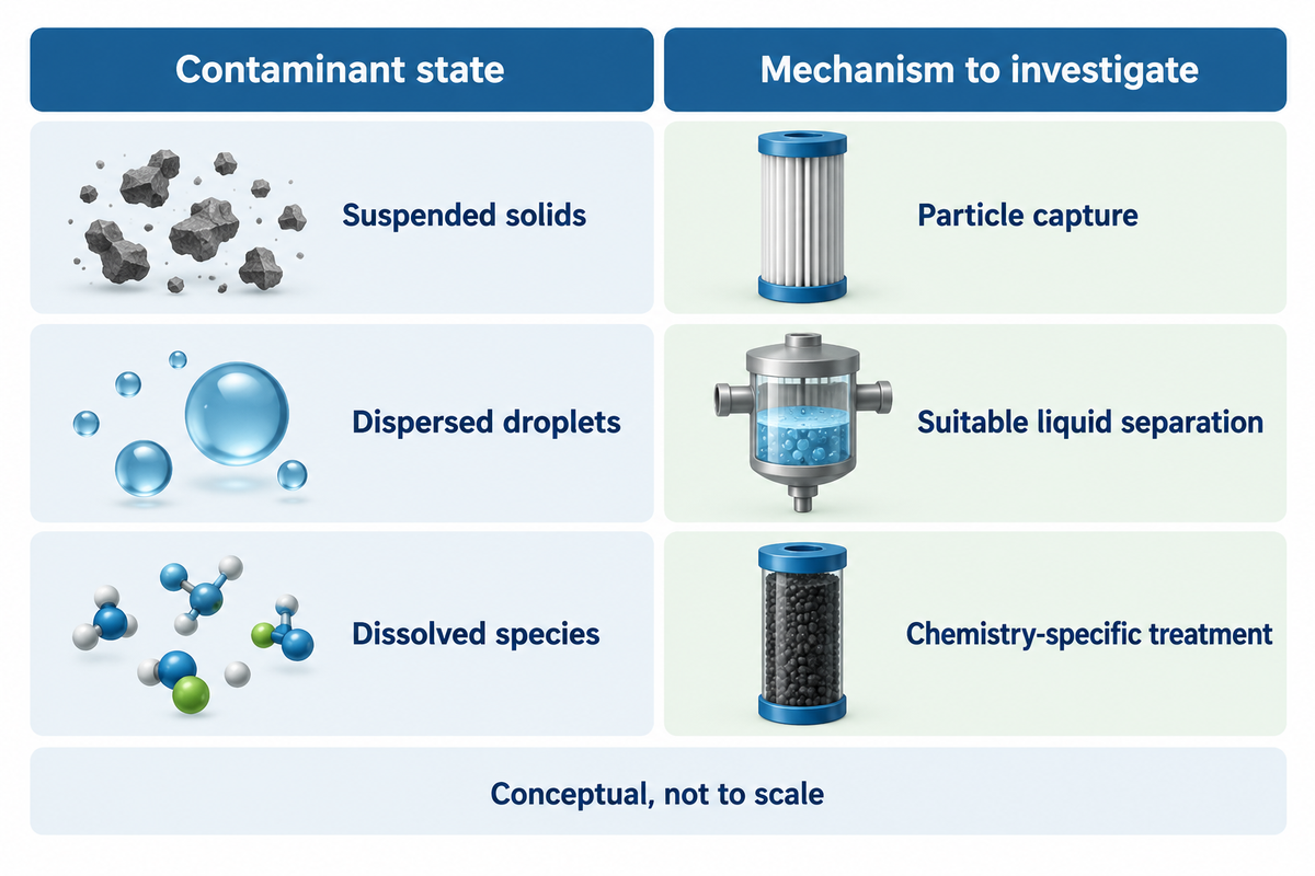
Mechanical particulate filters remove solid particles by interception and capture at the surface or within the medium. Droplet separation, adsorption and dissolved-ion removal use other mechanisms. Classify the unwanted component and then decide what filter is appropriate. Unwanted components such as dissolved components or a second liquid phase can give similar symptoms while requiring a different treatment.
The University of Georgia’s mechanical-filtration bulletin explains the distinction between suspended material and dissolved chemicals in water. The same physical distinction is useful in industrial discussions, while the bulletin’s household-water performance and maintenance advice stays within its original application.
Contaminant-State Evidence Grid
Use the grid to refine the diagnosis. Evidence identifies the observation beyond “the liquid looks dirty.” Multiple rows may apply to the same sample. Water and oil can occur in distinct phases or as a dispersion. A separator intended for bulk liquid separation solves a different problem compared to a particulate cartridge.
| Observed material | State to distinguish | Useful confirming evidence | Mechanism to investigate |
|---|---|---|---|
| Sand or silt | Suspended mineral particles | Paired solids or particle measurements | Mechanical straining or depth capture |
| Loose scale or rust | Suspended corrosion material | Solids identification and corrosion history | Particle capture plus the source of corrosion |
| Catalyst or other process fines | Suspended process solids | Composition, size distribution and batch history | Mechanical capture matched to the fines |
| Carbon carryover | Suspended carbon fines | Solids identification and carbon-bed history | Particle capture and carbon-stage condition |
| Gels or soft deposits | Deformable or compressible material | Microscopy or another suitable identification method | Retention under representative pressure and chemistry |
| Free oil layer | A separate liquid phase | Phase behaviour and oil identification | Bulk phase separation before polishing |
| Dispersed oil droplets | A liquid dispersed in another liquid | Droplet or emulsion characterisation | Liquid–liquid separation or suitable coalescence |
| Dissolved organic species | Molecularly dissolved material | Chemical analysis relevant to the process | Adsorption or other chemistry-specific treatment |
| Heat-stable salts in amine | Dissolved ionic contamination | Solvent analysis distinguishing salts from suspended solids | Solvent-management or ion-removal treatment |
What are the three types of filtration?
No universal three-type classification covers all industrial duties. Capture (or retention) can occur on the surface or in the depths. Coalescing filters bring dispersed droplets together, and adsorption targets selected dissolved substances. Filter cartridges can contain depth media in a pleated geometry, as illustrated in Hamlin and colleagues’ 2010 multilayer-media application for 3M Innovative Properties.
Example: Consider a solvent-polishing line with a hazy outlet following the installation of a new particulate cartridge. The operator thinks the cartridge is too coarse and suggests a finer one. Quality staff instead distinguish retained solids from dispersed droplets using a method suitable for the solvent. If solids fall while haze remains associated with the second liquid phase, the next decision concerns liquid–liquid separation. Purchasing, therefore, has a well-defined problem for which it can set a price rather than evaluate a series of increasingly finer elements. No change in appearance alone settles whether the product meets its chemical-quality requirement.
Both bag and cartridge systems play a role in suspended-solids control. Construction and retention dictate their application; the liquid filter bag range is a product reference when that format suits the established duty.
Decision point: expend the replacement budget on a particle filter for suspended-materials control; send problems of dissolved ions and stable emulsions to the pertinent evaluation and treatment.
Where does liquid filtration fit in chemical, petrochemical and oil and gas operations?
Liquid filters are widely used in process-liquid polishing, solvent circulation and industrial-water treatment. Filters used in the oil and gas industry also appear in liquid-side duties within gas-processing facilities. Conditions in gas streams dictate phase, flow, and equipment requirements. The position of a cartridge doesn’t make it a gas filter.
What Does Filtration Do in Oil and Gas Operations?
Filtration helps control identified contamination before it reaches a sensitive process step. In the oil and gas industry, that can mean solids in a hydrocarbon liquid, contamination in an amine circuit, or particles in utility water. Gas filtration applications address different streams, including gas supplied to compressors or burners, and require their own design basis.
The American Filtration & Separations Society’s amine overview describes the interaction of solids, hydrocarbons and solvent contamination. This is why a refinery or petrochemical industry discussion benefits from naming the stream and its quality objective before naming equipment.
Oil and gas filtration covers numerous fields. Crude oil, process condensate and treated water present different filtration problems. During refining and petrochemical production, process fluids can change composition between stages, so the duty belongs to the identified stream. Oil filtration for the removal of solids differs from the removal of the dissolved chemistry in a solvent loop.
Moisture separated from the gas still requires handling in the gas processing system. Gas filtration solutions therefore start with gas-specific conditions rather than a liquid-cartridge catalogue.
Multi-stage filtration systems assign a particular task to each stage. Filtration and separation solutions work in concert when the upstream stage produces a feed appropriate to the next mechanism. In petrochemical processes, a cartridge may polish liquid after a bulk separator; it shouldn’t assume the duty of separator because they’re situated in the same sequence. The sequence should follow the identified contamination and process objective.
High flow is relative to a cartridge format and doesn’t imply universal approval for a given liquid. Use the ECOFILTRONE high-flow product reference for that family after the liquid duty is defined.
What do cartridge construction and retention ratings tell you?
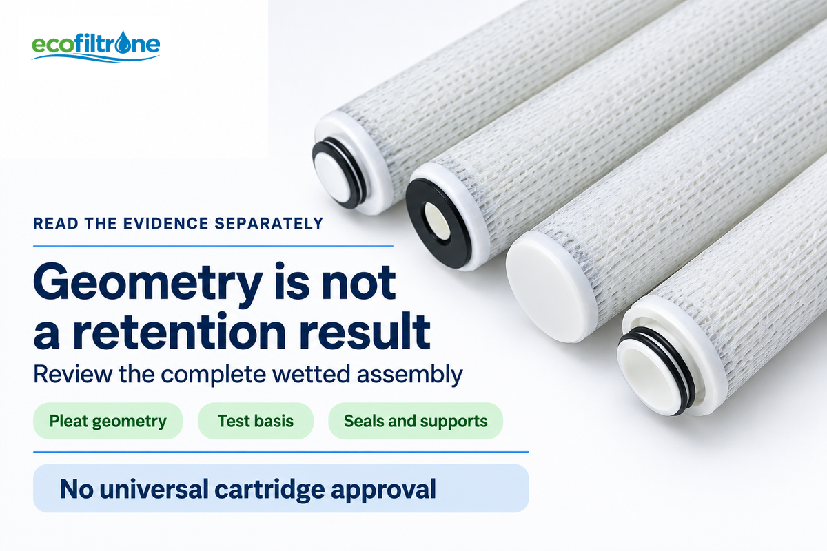
Construction describes the filter medium and assembly; a retention rating describes performance under a stated test basis. Efficiency, challenge, and test conditions must also be defined to assess a micron rating. Pleat geometry, seals and support parts also affect whether a filter element suits the installed system and intended liquid.
ISO 16889:2022 specifies a hydraulic-fluid-power multi-pass test with controlled contaminant injection. Its abstract describes test conditions for differential pressure, contaminant capacity and removal of particulate. A comparison should retain the test liquid, challenge and method rather than treating every capacity figure as a chemical-process service-life prediction.
Depth and surface describe the capture behaviour of a filter. Pleated describes geometry. Melt-blown and string-wound describe other constructions. Liquid filters are typically made as assemblies with several wetted parts: the medium, core, end caps, joining material and seals. Some filters use layered filter media, so a geometric description alone leaves the capture structure unresolved. A pleated medium may be surrounded by seals made of an incompatible material or an incompatible core.
How do liquid cartridge filters compare to other filtration systems?
Cartridge filters offer replaceable media for defined retention tasks. Bag filters provide another replaceable format; mesh filters and metallic filters provide mechanical screening. Self-cleaning filters provide a cleaning mechanism. Select among these filtration technologies using contaminant properties, required retention, loading and permitted maintenance, rather than assuming one construction is always better.
For details of pleated construction, the next appropriate references are in the pleated cartridge product family. Product configuration belongs with the specific element, not in a universal “best filter” table.
Soft contamination adds a further complication. In a 2019 microfluidic study by Bouhid de Aguiar and colleagues, deformable microgels passed model pores smaller than their original size. This laboratory result explains why a rigid-particle size comparison can fail for gels; it supplies no general industrial breakthrough pressure.
Engineering note: the public ISO 16889 abstract lists upstream challenge concentrations of 3 mg/L, 10 mg/L and 15 mg/L for its three test conditions. Those are method conditions, not recommended concentrations for a chemical plant. Keep a test result attached to its method when comparing filtration efficiency or dirt capacity.
Why can filter differential pressure change without failure?
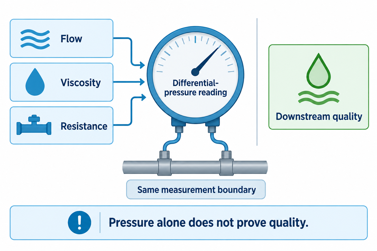
Differential pressure changes depending on flow, liquid viscosity, and resistance in the measured section. Accumulated solids can increase resistance, but a colder liquid or higher flow can also raise the reading. Compare readings from the same pressure-tap location pair and assembled filter system.
The pressure-filtration model described by Li and others, 2019 correlates flow rate of liquids to pressure, viscosity, and resistance of the medium and cake. The model was validated using a dead-end cell with glass beads and water. That gives a useful conditional explanation, rather than a universal correction factor for reactive liquids, emulsions or every housing.
Example: an operator records 0.2 bar differential pressure at 12 m³/h with a dynamic viscosity of 10 mPa·s. Later, the same flow requires 0.4 bar while viscosity is 20 mPa·s. For a fixed-resistance, laminar porous-flow model, expected pressure drop is 0.2 bar × (20 mPa·s ÷ 10 mPa·s) = 0.4 bar. The viscosity change alone is consistent with the pressure rise under those assumptions. The operator therefore keeps the two periods separate in the service-life comparison and checks the downstream-quality result. If the outlet fails acceptance, a successful arithmetic match doesn’t turn that run into a pass. Housing losses, changing cake structure or a second liquid phase would require a different interpretation.
An Eng-Tips hydraulic discussion illustrates the confusion between the pressure-flow curve for an empty housing and the element’s pressure flow curve. Treat the post as a ‘practitioner’ question and not as a validated model for chemical-filtration.
System pressure and differential pressure describe different loads. Vessel containment, element collapse resistance, and reverse-flow limits remain separate checks. A site-approved changeout point must respect the weakest applicable limit. Running to a structural maximum isn’t a service-life strategy. Record equipment performance against its intended function, for example, delivered flow or downstream pressure, rather than ranking filter by pressure drop alone.
Operating takeaway: a rise from 0.2 bar to 0.4 bar at unchanged flow has several possible causes. First, consider the feed viscosity and the clean baseline, and then interpret the quality result. Low pressure drop alone is equally incomplete: poor sealing, changed flow or an unsuitable mechanism can allow contamination downstream. Several mechanisms may permit contamination downstream; for example, an unsuitable seal may allow bypass.
What evidence makes two operating periods comparable?
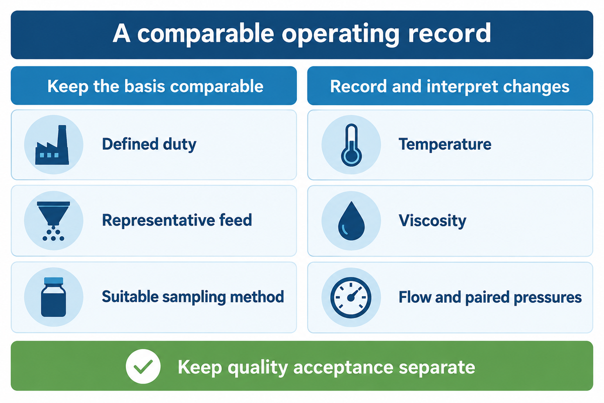
Operating periods comparable in definition use the same representative feed, defined duty, and measurement within agreed operating windows. Describe any variable that may change the result (e.g. temperature and viscosity). Separate quality acceptance from pressure. Before assigning an outcome to the filter, describe the differences when conditions differ materially.
ISO 11500:2022’s published scope describes light-extinction particle counting for clear, homogeneous, single-phase hydraulic-fluid bottle samples; its catalogue also lists a 2026 amendment. This illustrates the need to match an analytical procedure to the liquid. An appropriate analytical method for an opaque, emulsified, or multiphase sample is to be determined rather than to read a raw particle count.
Example: the following completed record holds flow and processed volume constant, but changes temperature and viscosity. The nominal suspended load is the same, however that alone says nothing about particle size distribution, deformability or chemical composition.
| Record field | Period A | Period B |
|---|---|---|
| Liquid identity | Same process liquid | Same process liquid |
| Reported suspended load | 20 mg/L | 20 mg/L |
| Flow | 12 m³/h | 12 m³/h |
| Temperature | 40 °C | 25 °C |
| Dynamic viscosity | 10 mPa·s | 20 mPa·s |
| Housing inlet pressure | 3.0 bar | 3.0 bar |
| Housing outlet pressure | 2.8 bar | 2.6 bar |
| Housing differential pressure | 0.2 bar | 0.4 bar |
| Cumulative processed volume | 600 m³ | 600 m³ |
| Downstream acceptance | Agreed method and limit required | Same suitable method and limit required |
Period B’s 0.4 bar reading can’t be ranked against Period A’s 0.2 bar reading as evidence of faster loading, without taking into account the difference in viscosity. At 600 m³, elapsed time is only meaningful if flow and interruptions were the same. Quality staff should retain the same sample locations and the same basis of analyses, including the relevant uncertainty and detection limit.
Any sampling or inspection is done following the site’s approved methods for the liquid and equipment. A measurement basis of an instrument is useful only if it fits the sample. Observations across representative conditions of service should be made before a general service life claim is made; the number of observations should depend on variability and the consequences of the decision.
Procurement consequence: Two offers which report “longer life” require a common end point. A run ending at a pressure limit is different from a run ending at an agreed quality limit, and neither can be replaced by the other in a silent substitution.
How do you investigate early plugging or dirty filtrate?
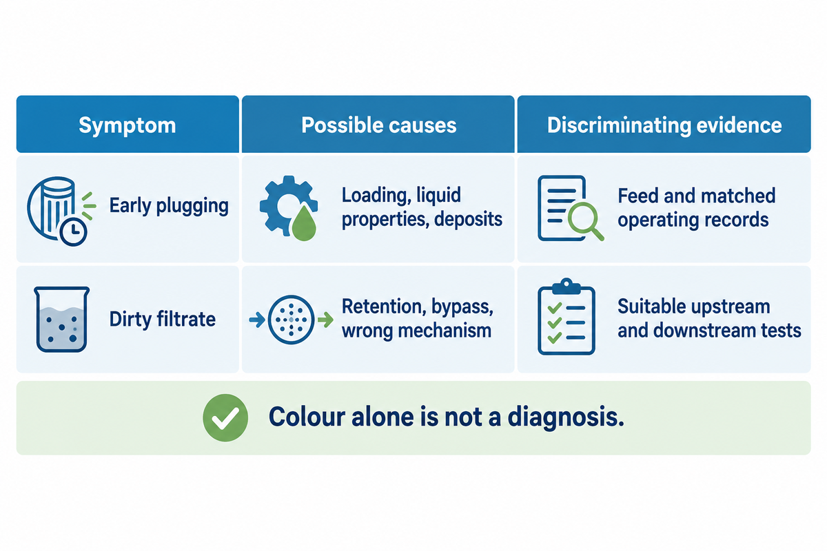
Separate symptoms from their possible causes, then use operations and quality data to better differentiate them. Early plugging can follow increased loading, changed liquid properties or a different deposit structure. Dirty filtrate can arise from poor retention, bypass or a contaminant that the selected mechanism does not address. Color alone isn’t a diagnosis.
The AFS amine-contamination article describes various causes of fouling and foaming. The author, David Engel, writes as a filtration consultant with Nexo Solutions and Sulphur Experts. He suggests looking at the process and the feed together.
“a proper evaluation by the plant of its process, equipment and feed composition is required”
| Observation | Competing explanation | Discriminating record | Decision |
|---|---|---|---|
| High pressure drop at a cold start | Higher viscosity or greater restriction | Temperature, viscosity basis and clean baseline at matched flow | Resolve the operating-condition change before ranking filter life |
| Higher pressure drop after a flow increase | Flow-related resistance | Actual flow and manufacturer pressure–flow information | Compare at the same flow or use a justified model |
| Faster pressure rise at matched conditions | Greater feed loading or changed particle properties | Upstream solids, fines distribution and batch history | Investigate the contaminant source as well as retention |
| Sudden pressure fall with dirtier outlet | Loss of retention, leakage or a flow change | Paired quality, flow and pressure records; approved assembly inspection | Escalate an unexplained quality failure |
| Low pressure drop with dirty liquid | Wrong mechanism, bypass or an unsuitable rating | Contaminant state and installed assembly identification | Establish why contamination reaches the outlet |
| Persistent haze after a finer element | Fine particles, droplets or dissolved chemistry | A method suited to the liquid and suspected contaminant | Choose the separation mechanism after identification |
| Black solids in an amine loop | Carbon fines, corrosion material or another solid | Solids identification and process history | Distinguish sources rather than diagnose by colour |
| Foaming persists after particle removal | Surfactants, hydrocarbons or interacting process causes | Solvent analysis and unit operating review | Treat foaming as a process investigation |
| Soft deposits pass or compress | Deformation, changing cake structure or chemistry | Deposit identification and representative retention trial | Evaluate quality under the intended conditions |
Heat-stable salts require special consideration in this case. They’re dissolved, ionic contaminants, and are different from black, suspended, particulate contamination. The 2019 study by Grushevenko and others used an amine model solution to remove salt by electrodialysis. Their lab work and energy results shouldn’t be taken as instructions on how to operate an amine unit.
A finer particulate filter may capture more of an identified solids fraction, but won’t remove dissolved salts by sieving. Activated carbon treatment, other solvent management and solids filtration interventions have distinct roles. The presence of a foaming problem, in the case of a particle-removal stage being implemented, shouldn’t rule out a unit investigation.
The differential-pressure article by Joe Bodle and Jay Jett in International Filtration News also discusses unexpected pressure decreases and process changes. Both work for Valin. Be aware of the supplier context when using application examples. Use a trend as an indication to investigate, not a universal threshold.
Maintenance takeaway: repeatedly replacing the same element can cover up an upstream source of contamination. A change that just extends the pressure interval while contaminated liquid reaches refinery equipment hasn’t achieved the protected process objective. Look into equipment wear and the associated contamination before claiming that a change will extend equipment life. An equipment lifespan claim needs an observation period and a defined failure criterion, not a filter-life proxy.
Where the objective is to prevent equipment damage from abrasive solids, measure the solids that matter and the affected equipment condition. Other causes of equipment damage can persist after a filter change. Improved process performance should be expressed as the intended result, such as accepted quality at the required flow, rather than a general promise of better process efficiency.
How should a controlled filter trial be evaluated?
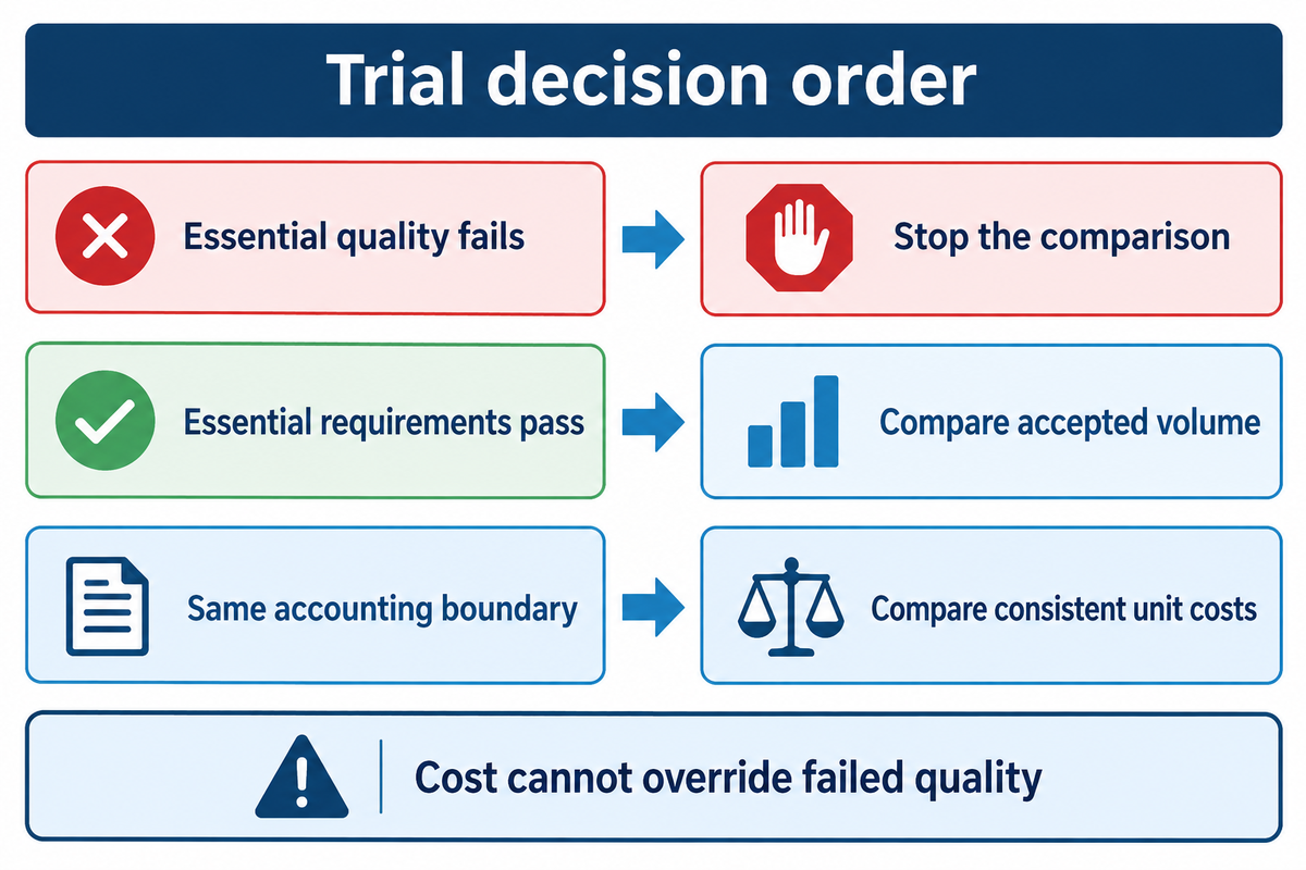
Evaluate a filter trial against an agreed quality requirement under representative, comparable operating conditions, then compare cost within the same accounting boundary. Reject a change that doesn’t satisfy essential quality or operating requirements. For changes that satisfy essential requirements, the accepted volume of liquid is a more meaningful cost measure than the total number of days or total volume of liquid circulated.
Matched-Condition Filter Trial
This proposed trial structure combines the operating variables in pressure-filtration research with the discipline of retaining the test conditions described in ISO 16889. It is an editorial planning method, not a new standard.
- Define acceptance. State the downstream-quality limit, suitable analytical method and permitted operating endpoint before the trial.
- Match the duty. Record feed identity, contamination, flow, temperature, viscosity and assembly configuration.
- Track the run. Keep paired pressure and quality records, cumulative volume, interruptions and excursions.
- Apply the quality decision. Separate passing output from rejected or unassessed liquid.
- Compare consistent costs. Divide the agreed cost total by accepted volume and report excluded costs explicitly.
Example: procurement is comparing two candidates for the same liquid-polishing duty. Both pass the pre-agreed quality requirement within the same representative operating window. Candidate A costs US$2,400 for consumables, labour and disposal and produces 900 m³ of accepted liquid. Candidate B costs US$2,700 on the same basis and produces 1,200 m³. Finance calculates A at US$2,400 ÷ 900 m³ × 1,000 = US$2,666.67 per 1,000 accepted m³. B is US$2,700 ÷ 1,200 m³ × 1,000 = US$2,250.00. B has the higher trial bill but the lower unit cost. Energy, lost production or disposal categories omitted from both totals must be shown separately before a purchasing decision.
| Common accounting boundary | Candidate A | Candidate B |
|---|---|---|
| Accepted liquid volume | 900 m³ | 1,200 m³ |
| Consumables, labour and disposal | US$2,400 | US$2,700 |
| Cost per accepted m³ | US$2.67/m³ | US$2.25/m³ |
| Cost per 1,000 accepted m³ | US$2,666.67 | US$2,250.00 |
| Required quality decision | Pass before cost ranking | Pass before cost ranking |
Quality is the hidden bottleneck. If B processes 1,200 m³ but only 800 m³ is accepted, then its same US$2,700 cost becomes US$3,375 per 1,000 accepted m³. If the quality of the product fails to meet an essential requirement, comparison must stop at that failure. The cost calculation can’t serve as approval to continue.
Filters are designed for defined duties, and a trial should preserve the differences that matter to those duties. Additional repetitions are necessary when batch variation, uncertain measurements or changing deposits may reverse the apparent ranking. Plant Managers should assess maintenance and the continuity of the supply; Finance should limit costs to those that share the defined boundary.
Fewer changes can reduce maintenance costs when saved labor and disposal outweigh any additional costs of element, energy and quality. Count the effects over the same accepted volume. The candidate that meets the operating and quality requirements is the right filter rather than the candidate that reports the longest calendar interval. This restricts claims about industrial equipment to measurable duties.
Key takeaway
A filter trial earns a cost comparison after it passes quality and operating requirements. Keep the denominator as accepted m³ and preserve the same cost boundary for every candidate.
Which evidence should be checked before approving a change?
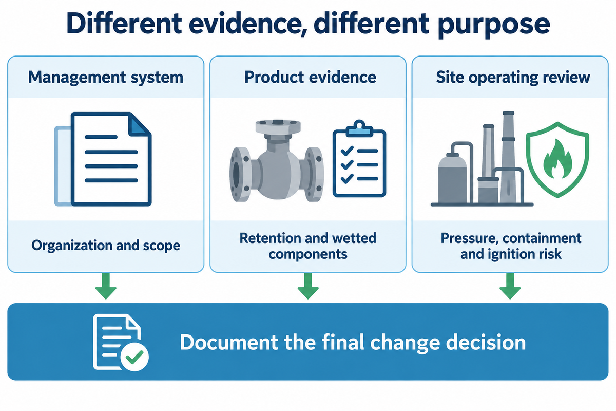
A change review should connect the intended contaminant removal, complete assembly, suitable operating envelope and downstream acceptance. Quality management certification, material records and product test results serve different functions. Review them against the specific liquid and installed equipment, with the site’s process-safety requirements governing the final operating decision.
ISO 9001:2026 addresses an organization’s quality management system. Product retention, material compatibility and hazardous-service qualification require their own relevant evidence. The certificate holder, scope, edition and applicable transition position require documentary review; an organization’s certificate is not a cartridge approval.
Accumulation of static charges during transfer of flammable liquids is discussed by the UK Health and Safety Executive. Chemical compatibility addresses material behaviour, while ignition risk, containment and pressure control require a system-level review. A change to the medium or liquid conditions should retain that review even if the result of outlet quality of the system improves.
The 2026 Water Reuse Action Plan update by the US EPA covers planned initiatives on treatment validation and reuse of oil and gas wastewater. Environmental regulations and reuse acceptance are likely to remain jurisdiction- and application-specific. The fact that a policy initiative doesn’t automatically imply one particulate filter makes a wastewater stream suitable for any reuse should be borne in mind.
Keep the approval record concise: contaminant and mechanism; assembly and wetted components; agreed operating window; suitable quality method; trial results and exceptions; applicable documents; and the person responsible for the final change decision. Unresolved quality or operating limits should be in the forefront of that decision.
Ecofiltrone is a Qingdao-based filtration products supplier and has engineering support. The company provides filtration consumables for industrial water and process liquids. We provide application review, filter selection, replacement matching and customized configurations. Our range of filtration products includes high flow, pleated, membrane, melt blown and string wound cartridges, and industrial liquid filter bags. For product configuration and a documented application, use our chemical and petrochemical filtration support.
One logical next step is to define a problem and present an operating record, rather than to seek the “best” filter. The right filtration objective states what must be removed and how the result will be judged. A plant team can then distinguish a consumable replacement from a change in treatment mechanism. Comparing filters for oil and gas systems begins with that same distinction.
Frequently Asked Questions
Why can liquid remain cloudy after a filter change?
Cloudiness can come from fine particles, dispersed droplets or dissolved chemistry that creates an optical effect.
A new element addresses only the contaminants its mechanism and retention characteristics capture. Identify the remaining material using a method suitable for the liquid, then compare upstream and downstream results. Clear appearance isn’t a complete purity test, and persistent haze alone doesn’t identify a damaged element. The UGA mechanism explanation separates particle capture from dissolved-chemical removal.
Can two filters with the same micron rating perform differently?
Yes. Efficiency, test conditions, medium and assembly construction can differ at the same stated micron rating.
A nominal size label leaves the retention definition unresolved. Compare the measured efficiency at the relevant size, the challenge material and the test conditions. Flow and liquid properties also matter in service. Two elements that physically fit the same housing may use different seals or supports, so procurement should retain the full configuration when evaluating a proposed replacement rather than matching only the label.
What does a sudden fall in differential pressure mean?
A sudden fall can reflect reduced flow, changed viscosity, a measurement issue or a loss of effective retention.
Read the pressure trend alongside flow, temperature and downstream quality. A decrease during a planned flow reduction has a different meaning from an unexplained fall at stable conditions with dirty filtrate. Any required inspection follows the site’s approved isolation and equipment procedures. The reading is an investigation trigger; it doesn’t identify the failed component or authorize continued operation on its own.
Does ISO 9001 certify a cartridge for sour service?
No. ISO 9001 certification concerns the organization’s quality management system.
Sour-service suitability belongs to the specific materials, components and operating conditions. Review the applicable product and equipment requirements separately from the supplier’s management-system certificate. Keep the actual certificate holder and scope with the approval record.
How many trial runs prove a filter will last longer?
There is no universal run count; representative conditions, variation and measurement uncertainty determine the evidence needed.
Begin with repeated, comparable runs and inspect whether feed quality, flow history or the endpoint changed. A single favourable run can reflect an easier batch. If differences between candidates are small compared with normal variation, collect more representative observations rather than announcing a life improvement. Define how interrupted runs and off-spec output are treated before comparing results. Quality personnel can select an appropriate analysis for the process and the decision’s consequences. Report the observed range and limitations with the result instead of assigning a confidence percentage that the trial design didn’t establish.
Should trial cost include off-spec liquid?
Include relevant costs within the agreed boundary and use only accepted output in the denominator.
Rejected output isn’t accepted production. Identify disposal, rework and other included costs explicitly. A candidate that misses an essential quality requirement fails that requirement even if a revised unit-cost figure appears attractive.
When is gas filtration outside this guide?
Gas-stream conditioning needs its own equipment and operating basis, even when the same facility also filters process liquids.
Natural gas, fuel gas and other gas-treatment duties involve stream-specific phase behaviour, contaminants and equipment limits. Liquid consumables used in an amine loop or utility-water system shouldn’t be presented as interchangeable gas-train components. A broader filtration project can coordinate several disciplines, including gas conditioning, but a gas or liquid assembly remains qualified for its intended stream. The filter format alone can’t bridge that difference.
Discuss the liquid duty with ECOFILTRONE™
Bring the contamination objective and operating record to a product-selection discussion.
Technical scope: industrial liquid-side filtration. Scenarios and worked figures are stated assumptions; they aren’t ECOFILTRONE plant results. Product and operating decisions remain subject to the relevant equipment documentation and site procedures.
References & Sources
- Mechanical Filtration: Methods and Devices, University of Georgia Cooperative Extension, reviewed 2026.
- Pleated multi-layer filter media and cartridge, US20100089819A1, Hamlin et al.; 3M Innovative Properties, published application, 2010.
- Amine Unit Contamination Overview, American Filtration & Separations Society; David Engel, 2024.
- ISO 16889:2022, hydraulic filter multi-pass test, International Organization for Standardization, public abstract.
- Microfluidic model systems used to emulate processes occurring during soft particle filtration, Bouhid de Aguiar et al., Scientific Reports, 2019.
- Predicting the performance of pressure filtration processes by coupling computational fluid dynamics and discrete element methods, Li et al., 2019.
- ISO 11500:2022, light-extinction particle-counting procedure, International Organization for Standardization, public abstract and amendment listing.
- Effect of Carbon Dioxide Loading on Removal of Heat Stable Salts from Amine Solvent by Electrodialysis, Grushevenko et al., Membranes, 2019.
- Preventing Filter Failure Through Differential Pressure Monitoring, International Filtration News; Joe Bodle and Jay Jett, Valin Corp., 2026.
- ISO 9001:2026, International Organization for Standardization, current public catalogue.
- Earthing: technical measures, UK Health and Safety Executive.
- Water Reuse Action Plan 2.0: Summer Update, United States Environmental Protection Agency, 2026.